Enlarge / The eye of Nintendo's legal department turns slowly towards a new target. (credit: Aurich Lawson)
Nintendo has filed a lawsuit against Tropic Haze LLC, the makers of the popular Yuzu emulator that the Switch-maker says is "facilitating piracy at a colossal scale."
The federal lawsuit—filed Monday in the District Court of Rhode Island and first reported by Stephen Totilo—is the company's most expansive and significant argument yet against emulation technology that it alleges "turns general computing devices into tools for massive intellectual property infringement of Nintendo and others' copyrighted works." Nintendo is asking the court to prevent the developers from working on, promoting, or distributing the Yuzu emulator and requesting significant financial damages under the DMCA.
If successful, the arguments in the case could help overturn years of legal precedent that have protected emulator software itself, even as using those emulators for software piracy has remained illegal.
![]()
Si vous êtes sous Windows et que vous voulez sortir des sentiers battus en le personnalisant un peu au-delà des paramètres prévus par Microsoft, vous êtes sur le bon site. Sur le site Windhawk, vous trouverez un utilitaire gratuit qui permet d’appliquer des mods à votre Windows.
Un « mod », c’est une modification qui sera faite à Windows pour par exemple avoir un notepad avec un thème sombre, faire un clic avec le bouton du milieu de la souris pour fermer une application ouverte dans la barre des tâches, ou encore contrôler le volume sonore de votre PC en scrollant sur votre barre de menu.
La liste complète des mods proposés par Windhawk se trouve ici et évidemment, le code de chacun d’entre eux est disponible donc vous savez exactement ce que ça fait sur votre système.
Il n’y a pas encore énormément de mods en base, mais c’est un bon début et vous pouvez proposer les vôtres.
En tout cas, pour moi qui aime ce genre de petits hacks, je trouve que c’est une chouette idée à développer.
You know we love a good cyberdeck around here, and we think you’ll love this video game emulator fresh from the latest issue of HackSpace magazine, out now.
We’ve only just finished printing a series on building a games cabinet using the RetroPie games emulator on a Raspberry Pi… and now something comes along that makes our plywood, full-size arcade machine look old hat.
This mostly 3D-printed cyberdeck features a 5-inch 800 × 480 touchscreen display, as well as the usual ports available through the Raspberry Pi 3 Model B+ that powers it. Quite how useful the screen’s portrait orientation will be for Sonic The Hedgehog is anyone’s guess, but if you’re playing any sort of top-down shooter, you’re laughing. The maker describes this project as a “video game emulator with some edge” – we think it’s pretty impressive for a project that began as an excuse to learn 3D design.
Each month, HackSpace magazine brings you the best projects, tips, tricks and tutorials from the makersphere. You can get it from the Raspberry Pi Press online store or your local newsagents.
As always, every issue is free to download in PDF format from the HackSpace magazine website.
The post RetroPie Cyberdeck | HackSpace #47 appeared first on Raspberry Pi.
Most of us use love and use the jq command. It works on Linux or Unix-like systems to extract data from JSON documents. Recently I found htmlq, which is like jq and written in Rust lang. Imagine being able to sed or grep for HTML data. We can search, slice, and filter HTML data with htmlq. Let us see how to install and use this handy tool on Linux or Unix and play with HTML data.
Love this? sudo share_on: Twitter - Facebook - LinkedIn - Whatsapp - Reddit
The post How to use htmlq to extract content from HTML files on Linux, macOS or FreeBSD appeared first on nixCraft.
In the latest issue of HackSpace magazine, Andrew Gregory meets Anna Ploszajski to explore the bit of the Venn diagram where making and materials meet.
Anna Ploszajski (pronounced Por-shy-ski) is a cross-channel swimmer, a materials scientist, a writer, and a breaker-down of barriers to scientific understanding. 50% of the HackSpace editorial team listen to her podcast, Handmade, from which has arisen a book: Handmade: A scientist’s search for meaning through making. Naturally, we wanted to talk to her to find out why we humans do what we do when we turn object A into object B. That’s a pretty big question, but if anyone can answer it for us, Anna can.
Anna Ploszajski: You say that, but I’ve been doing quite a lot of experiments in 3D printing onto fabric to try and make a 4D thing, because PLA has a kind of shape memory. I was wanting to do the experiment that I was doing (which actually I described at the end of the book). I’m trying to draw a conclusion about how my adventures in craft had also impacted my scientific research life. And the example that I use is this experiment that I did 3D printing onto fabrics.
What I was doing began with sort of pre-stressing, just normal textiles. I think there was a cotton, linen, pre-stressing it, just stretching them out with my hands, and then attaching them onto the print bed. And so, you already put in a kind of internal strain into the fabric, then 3D-print a very simple design that was either a circle, or just simple lines. And then obviously, when you print onto it, then the PLA plastic is bonded onto the textile. My idea was that if you then heated that material up, then it would soften, and that tension that you’d put into the fabric would be released. So that was my idea.
My project was all to do with exploring this idea of 4D printing. So printing, using 3D printing, to make objects that move in some way after you’ve printed them. The thing about it is, it’s adjacent to this topic of smart materials. There’s a family of materials that have some kind of smart property, usually it’s colour-changing or shape-changing in response to an external stimulus. So, that could be temperature change, or light levels or moisture levels.
And those smart materials are not actually that smart, it turns out, because what they do is really simple. Let’s take the example of a really simple shape change: wood is a really good example. It expands when it gets wet. And it contracts when it dries out. By our definition of a smart material, that is a smart material because it changes shape when there’s a change in environment. And that’s a very simple movement. And these smart materials tend to just have this kind of flip-flopping between two simple states – either, you know, an expanded state or a contracted state in this example. That’s not actually that useful, unless you can do a clever design to use that movement to form a clever kind of motion.
A really good example in nature is the pine cone; the spines of a pine cone have this really ingenious bi-layer structure, where one side of them has a very hygroscopic wood – it expands a lot when it gets wet. And the other side doesn’t expand a lot when it gets wet. So, when the pine cone gets wet, it’s that bi-layer structure that causes that movement. The wood itself is just expanding. But the contrast between the two is what causes that motion. So I was trying to get inspired by that and combine, using clever design, a quite simple, smart material with some design that would combine it with a non-smart material that would cause some kind of motion.
It’s all to do with stored tension, and triggering that tension release. And to be honest with you, I didn’t get very far with it. I understand the material side; that was fine. And I could do all my experiments in the lab, and I could characterise the materials fine, but I just don’t have a designer’s brain.
And that is what the book is about in a way: trying to access or tap into these other skills that designers and makers and craftspeople have which I don’t.
AP: I think that meeting all those craftspeople, and getting a view into their world, really gave me an appreciation for exactly how much work and time and skill and practice goes into really honing these skills. Wood is a really good example: when I did the wood carving workshop with Barn the Spoon, it took hours trying to make a spoon, but when I did it, mine didn’t look anything like
his spoons.
The skills themselves are often not that complicated or difficult to do. It’s the constant practice in refinement and design, which are the skills that I didn’t necessarily have.
AP: A few things. Firstly, I wanted to write a popular science book that didn’t cater to the normal popular science audience, by which I mean people who are already relatively interested in science, the types of people who would browse the popular science sections in a bookshop and pick things up about space, or the gut, or whatever. I feel like that audience is already very well catered for.
What I wanted to do was try and write a popular book that would be read by someone who would never normally read a science book – that’s the whole of the rest of the population. So you’ll notice in the book that there are a lot of scientific analyses and explanations, but they’re all quite short. And my hope was that, if someone’s coming at this with not very much prior knowledge of science, they
get to a description of the quantum mechanics behind why glass is transparent. But on the next page, we’re back to the story. And it’s really those stories that were the most important thing to me.
And so, in each of the ten chapters on different materials, the story isn’t the story of the material – it’s the story of something else. So in Plastics, it’s the story of my Polish grandad and, you know, his life story throughout the 20th century, which intertwines with the story of the rise and fall of plastics.
I wanted to draw all these other audiences in by storytelling, and then hopefully, sneak the science in when they weren’t looking.
The story of the book itself is to do with feeling very inadequate, I suppose. I had this realisation, having walked into the Institute of Making for the first time, that I was supposedly this expert in materials, having studied the science of it, having studied all on paper, but actually, there were all of these different people that had so much more in-depth knowledge than me. The craftspeople and the makers and the artists and the historians and the designers and the architects… And so it was them that I really wanted to spend time with and learn from.
That was four years ago. That was when I started my podcast, which is also called Handmade. And that was where I started interviewing makers and craftspeople. And the book just grew from that. Quite a few of the people that I interviewed on the podcast have ended up being featured in the book as the very, very, very kind craftspeople that took me under their wing and showed me the ropes of what they do.
To take blacksmithing as one example – I thought I was an expert in materials, but I had never felt metal softening under my fingers. Yes, I knew the theory, I could draw you the iron-carbon phase diagram, I could talk about the phases and melting, and all of the ways that carbon and iron interact at the atomic level inside steel. But I’ve never done it. And I didn’t know how hard you had to hit it to make it change shape. Agnes, the blacksmith who taught me, is just so, so brilliant. I’m such a huge fangirl of her. And it was very humbling, actually, to spend time with people like that.
AP: My favourite chapter in the book is Sugar, because it was the most fun story to write. And it’s the story of my English Channel swim. [Yes, you read that right – Anna has swum the English Channel.] One of the reasons was, I think, it already is one of the strongest chapters for storytelling. Because it is this kind of archetypal physical journey from A to B, but also a journey of discovery about yourself. And intertwined in that story is the story of sugar, and all its different forms, and how it affects the body and the mind.
In terms of the crafts, it was really wool that caught my imagination, and I’ve stuck with it. The story of wool is the story of my camper-van trip around Scotland and the north of England. I acquired wool from all these different places that I went to on my trip, and then knitted a patchwork blanket with all the wool I got from the different places. And through doing that, I taught myself how to knit and I met all of these kinds of amazing knitters and wool-craft people throughout Scotland and the north of England, and chatted to them and got an insight into this amazing world of women who knit – and they were all women – and what it means to them, and how it connects them. And it’s very meditative, I find, and that’s the craft that I’ve taken through since finishing the book a year ago. That’s the craft that I’ve continued with.
I don’t know what it is about it. It just feels so nice to create something, you know, especially in the last year when we were all sitting at home watching Netflix and trawling through the movies and TV shows on there. Although that felt like perhaps a bit of a waste of time, actually, if I was knitting while watching TV, it wasn’t all a waste of time; I had something to show for it at the end. And I think that’s what craft gives us – it’s a sense of purpose almost, and a sense of achievement at the end.
You know, to have that sense of achievement of ‘I’ve made this’ and now I can wear it, or now I can use it. I haven’t had that in science before. I only got that when I started entering this world
of craft.
AP: I’ve thought a lot about this: this kind of compartmentalising of making and science, or art and science as I talk about in the book (and I know that art and making are absolutely not the same thing). And I think there are a lot of reasons why the arts and sciences have been sort of severed from each other. In formal education, we separate them. At school, we have to often choose between those types of subjects. I ended up going down the science route, but I did A-level music. I love writing and music and history, and I was always crap at art, but I enjoy it. I think it’s really unhelpful that we do that, because it means that we brand people as ‘you’re a scientist’, or ‘you’re more of an artist’. And actually, I think the majority of people are probably somewhere in the middle. Actually, they have interest in both.
It’s a real shame that we often get siphoned off into these different camps, and often don’t get the chance to rediscover the other one. As someone who was siphoned off into the scientific track, it was really liberating to be able to discover the craft and artistic world. It was, like I say, very humbling. It was also really nice to be a complete beginner again at something, to be able to ask the silly questions from a place of curiosity, with no pressure, no educational pressure. I wasn’t trying to achieve anything apart from trying to make a spoon, or forge a knife, or throw a pot, or whatever it was.
Materials is a really interesting subject because it can sit at this intersection between the artistic world and the scientific world. Materials, perhaps uniquely in the sciences, is a really lovely way to explore the more artistic side. And what I’ve discovered through the book and through the podcast, is that we all understand these materials, maybe in slightly different ways. But quite often, it’s just that we use different language to talk about them. I remember interviewing a silversmith on my podcast called John Cussell, who described cold-working silver metal to me as making the atoms angry. So, when you cold-work silver, it becomes more and more stiff. I would describe that as putting dislocations into the material and putting internal stresses and strains to make them more brittle. We’re both talking about the same thing in different ways. And I think that, really, the wonderful thing that I love about materials is that it can be this common substance, literally, through which all sorts of different people can talk to each other.
AP: That’s my life’s mission, to try and break science out of universities through doing things like writing the book and the podcast, and the talks that I give. I really want to invite people in and show them that science – it’s a huge cliché but science really is everywhere. It’s never been more important than in the last 18 months to understand science, virology, how contagions spread – that’s all science. And the science communication that’s going on around that has been mixed. Some of it’s been really good, but some of it’s been really damaging. That’s what’s important to me is to break science out of these institutions, because a lot of people are turned off science at a very early age. And unlike a lot of other areas, it’s impossible to turn back. If you go down a non-scientific route, through school, and then maybe through university or through a job, it’s impossible to go back on that and pick it up again later. I feel like subjects like history and literature are much more accessible to everybody. Whereas science is considered to be more for a select few, you know, a chosen few who are allowed to do it. And that’s really not fair.
AP: I think you’d have to ask them, but whatever it is they do is experimentation, right? And they do experiments all the time – what temperature do I need to make my steel to make it do X? Or, what composition do I need my clay to be to make it do Y? How do I do the settings on my furnace to make sure that my pots don’t explode? And that is exactly the sort of stuff that we would do in the lab, you know: methodical experimentation. So in that way, definitely. I can’t see that there’s any difference at all between that. And in terms of the way that craftspeople and scientists think, that’s much more difficult to answer.
Most science has arisen from craftspeople and early experimenters. The subject of material science arose out of the subject of metallurgy, which arose out of blacksmiths like Agnes. If you go back far enough, it’s all the same thing.
Each month, HackSpace magazine brings you the best projects, tips, tricks and tutorials from the makersphere. You can get it from the Raspberry Pi Press online store or your local newsagents.
As always, every issue is free to download from the HackSpace magazine website.
The post Meet Anna Ploszajski: Where making and materials meet appeared first on Raspberry Pi.
In the latest issue of HackSpace magazine, Ben Everard tests whether a bit of kit from Spotpear can turn Raspberry Pi Pico into a games machine.
The snappily named Raspberry Pi Pico display 1.54-inch LCD by Spotpear ($11.89) brings in a 240×240 pixel IPS screen and ten buttons in a joypad-like arrangement. There’s four for direction, four for action, a select, and a start. At least, they’re labelled like this. You can use them for anything you like.
To help you get started, there’s a short manual, which includes example code for MicroPython and C.
This example code is easy enough to use, but it is a little messy. The mechanism for controlling the hardware isn’t separated into its own module, so you’re left with either the task of building the library yourself or having slightly untidy code. Not the biggest inconvenience, but compared to how neatly some maker hardware companies manage their code, we found ourselves off to a disappointing start.
There are also some sample UF2 files included along with the C example code, but these appear to have been built for different hardware and work either partially or not at all. The actual example code did compile and work properly.
When we ran the example code, we were impressed with the quality of the screen. With 240×240 pixels in just 1.54 inches, there’s a high pixel density that can give crisp graphics. Obviously, high pixel densities are a double-edged sword. While they can look great, it does mean higher RAM use, more time transferring data, and more data to process.
Fortunately, Pico is well-suited to the task of driving screens. Each pixel can take 16 bits of colour data, so a full-frame buffer is just 115,200 bytes. The display data is transferred by SPI, and Pico has a maximum SPI frequency of half the clock speed. For MicroPython, that means 62.5MHz. The actual data transfer rate is a little less than this because of overhead of the protocol, but we were able to drive full-frame refreshes at over 40 fps, which is plenty for smooth animations.
Obviously, if you’re looking to do animations, sending the data is only half the story. You also need to calculate the frame before it’s displayed. If you’re using MicroPython, you are quite limited by the amount of processing you can do and still keep a high frame rate (though you could use the second core to offload some of the processing). With C, you’ve got much more scope, especially as you could potentially offload the data transfer using direct memory access (DMA).
The one disappointing thing about the screen is that there’s no control over the backlight. According to the documentation, it should be attached to pin 13, but it isn’t. You can’t turn it on or off – it’s just permanently on, and quite bright. That’s a deal-breaker for anything running off battery power, as it will suck up a lot of power. However, if you want a display permanently on, this might be perfectly acceptable.
While we were quite impressed by the screen, we can’t say the same for the other part of the hardware – the buttons. They’re small, stiff, and have very little movement. The end result is a button that is hard to press, and hard to know if you’ve pressed it. They’re the sort of buttons that are commonly used as reset buttons as they’re hard to accidentally press.
We had hoped that this screen would make a good base for a games console, but unfortunately these buttons would just make for a frustrating experience. They might be OK for a menu-driven user interface, but that’s about it.
Another minor annoyance in this is the lack of any mounting holes. This makes it hard to embed into a project as the user interface.
We wanted to like this project. It’s got a good, high-res screen and a nice layout of buttons. However, the choice of components makes it hard to see how we’ll use this in our projects. We’re considering removing the surface-mount buttons and soldering wires onto them to make a more useful device, but if you’re going to go to that level of surgery, it’s probably better to start with a plain screen and work your way up from there.
5/10
Good screen, but awful buttons
Price: $11.89
Each month, HackSpace magazine brings you the best projects, tips, tricks and tutorials from the makersphere. You can get it from the Raspberry Pi Press online store or your local newsagents.
As always, every issue is free to download from the HackSpace magazine website.
The post Add 57,600 pixels to your Raspberry Pi Pico appeared first on Raspberry Pi.
Laura Kampf, the Köln-based wood and metalworker with a mild tiny house and Leatherman obsession sat down (virtually) with Alex Bate to talk about prison tattoo machines, avoiding your nightmares, and why aggressive hip-hop and horror movies inspire her weekly project builds.
Smudo the workshop dog was also there, which seems to be becoming a recurring and pleasant feature of HackSpace magazine interviews.
Laura: Yeah, that’s absolutely it. I mean, I document it for YouTube because I’m aware that this is the only place for me. And the documentation, that’s the work part, like setting up the camera, thinking about the story. But the physical work of building something, that’s a form of meditation. That’s just my happy place. And I know I have to document my work because I have to do something to make a living, right? I can’t just play. So YouTube is my work. But making is just, it’s just what I do, and I feel more and more that this is the only place for me.
And this is probably how musicians feel when they are performing on stage. You know, this – being in my shop, I feel so comfortable. And I feel so good. I don’t have that anywhere else.
My brother is super-creative, but my parents, not so much. My grandfather was an engineer. So I think
it kind of skipped a generation.
In design school, there was a project where we had to build something out of everyday objects. And it was for us, the designers, to get away from the computers and just do something with our hands. I built a tattoo machine, like a prison-style tattoo machine. And I was hooked. I remember coming home and I was so moved by the whole thing. Even though the machine looks terrible, everything fell into place.
Because all my life, people were telling me you need to find this one thing that you’re really good at and then just keep doing that. I think it’s also a German thing, you know, like, be perfect at one thing, and then you’ll be the best in your field. And I could never focus on one thing and building this tattoo machine; there were so many different things coming together.
I had all this interest in so many different fields and I could use them for the project – I enjoyed drawing fonts and learned how to do old-school tattoo lettering, and I could do a little bit of electronics to hook up a switch. All these things, I thought it was super-interesting. It was the first time I could just use little bits of everything I knew to make something that was really cool, and I was hooked after that.
I wanted to and then, thank God, because I was really young, it’s very likely that I would have done that, a tattoo artist came by and I showed him the machine, and he was like, “Don’t do it. It’s running way too fast. You will make mincemeat out of your skin”. But I bought pigs legs and pig’s ears and tattooed them. I couldn’t eat pig for probably two years after that. It was so warm, and tattooing the piece for a couple hours, the fat was running out of it – it was disgusting.
Looking back, I remember the little things that I made; when I showed them to people, they just didn’t show the same excitement for them as I did. And it was such a disappointment until I realised that no, the stuff I was making was really bad. That’s why no one was excited, because I didn’t know what I was doing. Once I got better and better, and especially with YouTube and talking to the community – well, I’m preaching to the choir here; everyone knows making is fantastic, and we have a very focused, niche community – and they get it.
I didn’t to begin with, I have to say. In the beginning, I felt more that it wasn’t about me, it was about the things that I make, and my sexuality and my gender don’t play a role in this. I don’t think about my sexuality all day long; I don’t think about the fact I’m a girl all day long, so why would it be in my videos? But I have to say that I changed my mind about these things. Because visibility is really important.
I had this really weird experience at the 10 Maker event a few years ago. I was wearing this T-shirt I got for free on one Christopher Street Day, it says ‘Gay Okay’. I love that shirt; it’s a really nice fit. I went to get some groceries with Brett from Skull and Spade and Hassan from HABU, and there was this girl, maybe eleven or twelve years old, and she saw me wearing that shirt, hanging out with regular dudes, doing regular stuff in a regular supermarket, and her jaw dropped. We were in the countryside, you don’t see things like rainbow flags there. And I could tell she’s maybe gay too, and it was so good for her to see that. There’s nothing different about you – you can still hang out with guys, you can still, you know, go shopping and all these things. That’s when I realised, institutions like Christopher Street Day are so important, but it’s also important to just have it integrated into regular stuff, not just special occasions. Today’s International Women’s Day? Well, we need to celebrate girls every day; every day you need to celebrate these things.
So, I kind of made it a habit to have rainbow flags in my videos. Not every video, and never super-obvious, but in the background, when I talk to the camera sometimes. I do wear my Gay Okay shirt every once in a while. I don’t want to make it a point because people like to put you in drawers. And, once you’re the queer maker, you’re the queer maker, and that’s all people want to talk about. And I don’t want that because I still think, at the end of the day, it’s about the things I build and not about me and my sexuality and gender. But, yeah, to just sprinkle it in every once in a while, I think it’s very important.
I don’t get much negativity about this. I was surprised, pleasantly so, obviously, but yeah, a couple of days ago, I wore my Gay Okay t-shirt in my Instagram Stories, and people applauded me for it, and that’s really interesting. I would never have thought that.
I think, at the beginning of my YouTube career, I was growing really fast and really, like, exponentially. And I had a couple of videos that went viral, like the beer bike, that went outside of the community. For those viral videos, you get negativity. They don’t know who you are, they don’t know the context, they don’t know what I’m doing. That’s why I hate having viral videos. It brings in the worst. I like to be in this little lake, surrounded by my followers.
Yeah, they take you out of context. Those people, they see one of my videos, they don’t know that I’m building something. And that’s another interesting thing that your community learns about you. They know I build something every week for the past six years. Every week, it can’t be the Holy Grail every freaking week. Sometimes it’s bad, but it’s stuff that I did that week – it’s documentation.
When I was a kid, I remember my mind was blown that The Simpsons had a different intro every episode. Something different happens every time. I couldn’t believe that, and how much work went into it. I think it primed me for being a weekly creator.
Haha, but not every video is a good idea. Some of them are really bad ideas. But that’s my privilege, you know, that I can still do that. Because I have to, otherwise there wouldn’t be a video, and I love that because the pressure helps me keep going. And the process is the same. It doesn’t matter if you’re building a tiny house or a scratch post for a cat. The process is me, being in the shop, listening to podcasts, listening to music, enjoying my tools, playing with the material – it’s all the same, it doesn’t really matter.
So, the public bench stuff that I’ve been doing lately, I get so many questions like, “Oh no, how could you leave the bench” and, like, I don’t give a damn about the bench. It’s not the bench, it’s the process that I enjoy. I could literally throw everything that I build away – I could throw it in the trash right away. I wouldn’t mind. I’m so focused on the process.
I was expecting it to break eventually. And, to be honest, I was kinda hoping for it because I wanted to do it again. And, this time, I’m actually hoping for it to get broken again because I want to do it again.
Yeah, it’s a very broad description of this, but the craftsmanship in Germany is of a very high standard, right? At least we like to think so. So, if you want to be a carpenter, you’re first an apprentice for three years or so, then you can be a carpenter and work under a master carpenter. If you want to educate other apprentices, or if you want to sell certain furniture, I think chairs is one of them, then you have to be a master. And it’s the same for every field. I think the most plausible is electricians. If you are not a master electrician, you cannot, say, make a lamp and sell it.
But my interest is so general. I wanted to make lamps, but the notion of designing a lamp that’s made out of wood and then obviously has electricity in it, it’s just impossible.
I spoke to the TÜV and asked them, if I design a lamp and want to sell it in a store, how do I do it. And I would have to get it checked by their institution, which is a couple of hundred euros, and get a certificate. But I would have to do this for the next lamp design, and the next. And that makes them so expensive. I can’t sell a lamp for 150 euros if it costs me more than that to get it checked. I’m not interested in mass production, I want to make one-off pieces.
I had already quit my job when I discovered this and remember having a big knot in my stomach thinking, ‘what do I do?’, and YouTube was the answer.
Yeah, there are loopholes – this is not a lamp, this is art. But, when I quit my job to become a self-employed lamp seller, I really only quit my job because I hated working for other people, not because it was my dream to sell furniture and lamps. I didn’t know YouTube really existed as a thing for me, and once I figured out people were actually making money off this, I was like, OK, I need to get a camera, I need to give this a try. Because that would be better than building stuff to sell it. I wasn’t interested in selling stuff. I don’t want clients. I don’t want that pressure from anyone else except me, so YouTube worked out perfectly for me.
It was. It was a great job, but it wasn’t for me. It was probably the perfect job, but I am not a good employee. I was asked a couple of years ago if I would do a talk about my career and how I made this job for myself and followed my dreams, blah, blah. I don’t like ‘follow your dreams’. It was the other way around. I avoided my nightmares. That’s how I got here. I never dreamed of this, I didn’t know this existed. So, I think avoiding your nightmares is much more efficient than following your dreams.
It’s more, and this is hard to explain, but I have this internal measuring unit of how much work should go into a project. I know how much time I can put into a project, and there’s this bucket of work I’ve put into it, and depending on how full the bucket is determines how the project looks and whether I use pocket holes or dovetails, for example.
All YouTube. That’s the cool thing. It’s all full circle. There are some things – I had a couple of jobs where I learned some skills. I worked as a flight case builder for three years, just filling those black flight cases. Which sounds very, very trivial. It’s not though, It’s crazy. You have to work so precisely, otherwise, the catches won’t close and all these things, and everything is building boxes. So I learned a bunch of stuff there. It was my Karate Kid apprenticeship. But a lot of it is YouTube. I remember watching Jimmy DiResta – I saw his TV show online, and then I watched a bunch of his videos without realising it was the same guy. Eventually, I noticed he had a weekly schedule and a podcast, and it was all exactly what I needed to see and hear. Right when I quit my job and I couldn’t sell lamps, there were these people telling me that they do this for a living. It was perfect timing. I feel like I’m the second generation YouTuber and they’re the first.
I like to listen to a lot of hip-hop, like super-aggressive hip-hop that is the complete opposite of me and has nothing to do with my world. And I like to watch horror movies, super-scary and bloody horror movies. I like to explore the opposite of what I have. A view into a completely different world. The Fantasy Filmfest is a huge inspiration for me. These movies that go right to DVD; they don’t go into the big theatres. I like to think about how they got made? How did they think of that? That’s the biggest inspiration. And, with hip-hop, the personas, and why they feel like they do, and how do they come up with those lines. They’re in their own universe, they have their own rules. I just love that. It’s how I feel when I’m building stuff. I’m telling myself a story that I don’t know the ending of. I don’t like to make sketches, I don’t like to know if it works. If I see someone else had the idea and did a full video about it, I don’t even want to do the idea anymore. I want to have that unknown. This is the idea, this is the stuff you have, now try to make it happen.
I don’t know if you saw it on Instagram, but I bought a Multicar. It’s so good. It’s the slowest car ever; it is painfully slow – 45 kilometres an hour and that’s it. But it has torque; you can tow pretty much everything with it. So my plan is to take the world’s smallest pub that I built a couple months ago and put it on at the back of the Multicar.
Something is holding me back at the moment, though. I have all the parts, I should be able to do it, but I don’t know what it is. I experience that quite often – I have an idea, and everything should be good to go, but I’m not doing it. And then, eventually, it turns out I wasn’t sure about the colour, or something else that was missing that I didn’t know at the time. So I don’t push it. But that’s the project I’m looking forward to.
I don’t know. Like, that’s the one thing that I’m really scared of, like, what happens when I get sick? Because at the beginning of the year, I hired my best friend. So now we’re both relying on my mental and physical health. So I think it’s a good idea to broaden stuff and have more income streams. I love doing the TV stuff [Laura recently started presenting a new TV show], because whenever I’m working with the TV people, I think, like, oh man, I love YouTube. And, when I do too much YouTube, I start really looking forward to working with actual professionals again. It’s a cool balance. I kind of hope that I can keep doing this. You know, I think it’s really cool. And as I said, there’s no other place for me. Where would I go?
I think I would like to actually have a couple of products now. Some of the furniture I’m building, if you look at them in a different context to ‘this is just what I built this week’ and is only the product of seven days’ worth of work, I think some of those ideas aren’t that bad. And if you put some more work into them, they could be pieces that would sell. But I would want someone who takes the prototypes and does the whole production for me. I’m not interested in all that. But I think it would be cool to have a line of plywood furniture.
A newspaper interviewed me about the bench. And for the interview, they also approached the city saying, hey, wouldn’t you want to work with her? And you know, maybe collaborate on this because this might be a cool thing. And they said that they don’t have the personnel. But honestly, if they would have done it, that would have made it so boring. Working with somebody in an office telling me where the broken benches are so I can go and fix them. That’s a job.
Until I hit publish, I feel like that every week. It feels like I’m just making it for myself. I talk very positively about YouTube, and that’s genuinely how I feel about it, but sometimes it’s really hard on me because I’ll work seven days on a video, think it’s the best thing I ever did, and it makes me so happy. I’ll edit it for hours, sink all this time into it, all this energy, and then the video tanks, and it kinda ruins it for me. I’m in a super-good mood right now because the bench video did so well, and people understand what I’m trying to say. But, there are other cases where it doesn’t work as well, and where I feel like I’ve dropped the ball and couldn’t get my excitement across. And that’s always super-disappointing because I’m always excited about the stuff I make; I always have some angle I find super-interesting, otherwise, I’m not motivated to do it. And, when the video tanks, it makes me feel like I lost the opportunity to spread that excitement, to spread that motivation, and that feels like I wasted my time. And that’s the downside of YouTube.
I mean, I think every creator takes it in a different way. And you need to find a way to deal with this, and it’s really important to talk about it. This is my dream job and I can do whatever I want to do as long as I don’t drop the ball. I hired my friend, so now I can’t drop the ball for the both of us.
Laura Kampf produces a video every Sunday on her YouTube channel. You can also follow her on Instagram and, for any German-speaking readers, her podcast – Raabe & Kampf – with friend and journalist Melanie Raabe can be found wherever you listen to podcasts.
Each month, HackSpace magazine brings you the best projects, tips, tricks and tutorials from the makersphere. You can get it from the Raspberry Pi Press online store or your local newsagents.
As always, every issue is free to download from the HackSpace magazine website.
The post Meet Laura Kampf: Wood and metalworker appeared first on Raspberry Pi.
When we saw Alex Glow’s name in the latest issue of HackSpace magazine, we just had to share their project. HackSpace #45 celebrates the best Raspberry Pi builds of all time, and we remembered spotting Alex’s wearable robotic owl familiar back in the day. For those of you yet to have had the pleasure, meet Archimedes…
Back in 2018, Hackster’s Alex Glow built Archimedes, an incredible robot companion using a combination of Raspberry Pi Zero W and Arduino with the Google AIY Vision Kit for its ‘brain’.
An updated model, Archie 2, using Raspberry Pi 3B, ESP32-powered Matrix Voice, and an SG90 micro-servo motor saw the personable owl familiar toughen up – Alex says the 3D-printed case is far more durable – as well as having better voice interaction options using Matrix HAL (for which installer packages are provided for Raspberry Pi and Python), plus Mycroft and Snips.ai voice assistant software.
Other refinements included incorporating compact discs into the owl’s wings to provide an iridescent sheen. Slots in the case allowed Alex to feed through cable ties to attach Archie’s wings, which she says now “provide a lively bounce to the wings, in tune with his active movements (as well as my own).”
Each month, HackSpace magazine brings you the best projects, tips, tricks and tutorials from the makersphere. You can get it from the Raspberry Pi Press online store or your local newsagents.
As always, every issue is free to download from the HackSpace magazine website.
The post Archimedes the AI robot | HackSpace #45 appeared first on Raspberry Pi.
In the latest issue of HackSpace magazine, Ben Everard shows us how to create a framework for building audio devices using Raspberry Pi Pico, called PicoPicoSynth.
Raspberry Pi Pico combines processing power with the ability to shuffle data in and out quickly. This makes it a good fit for a lot of different things, but the one we’ll be looking at today is sound synthesis.
There are a huge number of ways you can make sound on a programmable electronic device, but there’s always space for one more way, isn’t there? We set about trying to create a framework for building audio devices using Raspberry Pi Pico that we’ve called PicoPicoSynth, because it’s a small synth for Pico.
The program is powered by a sequencer. This is a structure that contains (among other things) a sequence of notes that it plays on a loop. Actually, it contains several sequences of notes – one for each type of noise you want it to play. Each sequence is a series of numbers. A -1 tells the sequencer not to play that note; a 0 or higher means play the note. For every point in time (by default, 24,000 times a second), the sequencer calls a function for each type of noise with the note to play and the time since the note first sounded. From these inputs, the callback function can create the position of the sound wave at this point, and pass this back to the sequencer. All the sounds are then mixed and passed on to the Pico audio system, which plays them.
This setup lets us focus on the interesting bit (OK, the bit this author happens to find interesting – other people may disagree) of making music. That is playing with how manipulating waveforms affects the sound.
You can find the whole PicoPicoSynth project at hsmag.cc/GitHubPPSynth. While this project is
ongoing, we’ve frozen the version used in this article in release 0.1, which you can download from hsmag.cc/PPSythV1. Let’s take a look at the example_synth file, which shows off some of the features.
You can create the sound values for PicoPicoSynth however you like, but we set it up with wavetables in mind. This means that you pre-calculate values for the sound waves. Doing this means you can do the computationally heavy work at the start, and not have to do it while running (when you have to keep data flowing fast enough that you can keep generating sound).
The wavetables for our example are loaded with:
low_sine_0 = get_sinewave_table(50,24000);
low_sine_1 = get_sinewave_table(100,24000);
bongo_table = create_wavetable(9054);
for (int i = 0; i < BONGOSAMPLES; i++) {
bongo_table->samples[i] =bongoSamples[i] * 256;
}
The first two create sine waves of different frequencies. Since sine waves are useful, we’ve created a helper function to automatically generate the wavetable for a given frequency.
The third wavetable is loaded with some data that’s included in a header file. We created it by loading a bongo WAV file into hsmag.cc/WavetableEd, which converts the WAV file into a C header file. We just have to scale it up from 8 bits to 16 by multiplying it by 256. There’s no helper function to do the job here, so we have to load in the samples ourselves.
That’s the data – the other thing we need are the callback functions that return the values we want to play. These take two parameters: the first is the number of samples since the note was started, and the second is the note that’s played.
int16_t bongos(int posn, int note) {

          if (note == 0 ) {
                      return no_envelope(bongo_table,
1, posn);
}
if (note == 1 ) {
return no_envelope(bongo_table,0.5, posn);
}
else {
return 0;
}
}
int16_t low_sine(int posn, int note) {
if (note == 0 ) {
return bitcrush(envelope(low_sine_0, 1, posn, posn, 5000, 10000, 15000,40000),32768,8);
}
if (note == 1 ) {
return bitcrush(envelope(low_sine_1, 1, posn, posn, 5000, 10000, 15000,40000),32768,8);
}
else {
return 0;
}
}
The note is 0 or higher – it corresponds to the number in the sequence, and you can use this however you like in your program. As you can see, both of our functions play sounds on notes 0 and 1.
The library includes a few functions to help you work with wavetables, the main two being
no_envelope and envelope. The no_envelope function also takes a multiplier – it’s 1 in the first instance and 0.5 in the second. This lets us speed up or slow down a sample, depending on what we want to play.
An envelope may be familiar to you if you’ve worked with synths before, and it’s used to convert a constant tone into something that sounds a bit like an instrument being played. You supply four values – the attack, decay, sustain, and release times. During the attack phase, the volume ramps up. During the decay phase, it partially drops to a level that it holds during the sustain phase, and finally it drops to 0 during the release phase. This gives a much more natural sound than simply starting or stopping the sample.
The envelope function also has a multiplier, so we could use the same wavetable for both, but it’s more accurate to generate a specific wavetable for each note if you’ve got the space to store it.
There are also a few sound effects in the synth library that you can apply – BitCrunch, for example. This compresses the sample bit depth down to give the sine wave a distorted sound.
These callbacks don’t have to be sound. You could equally use them to co-ordinate a lighting effect, control physical hardware, or do almost anything else.
Now we’ve got the sounds set up, it’s time to link them all together. This is done with the code below.
int bongo_sequence[] = {1, 1, -1, -1, -1,0, -1, -1};
int low_sine_sequence[] = {-1, -1, 1, -1,-1, -1, 0, -1};
struct sequencer main_sequencer;
init_sequencer(&main_sequencer, BEATNUM,BEATFREQ);
//add up to 32 different sequences here
add_sequence(&main_sequencer, 0, bongo_sequence, bongos, 0.5);
add_sequence(&main_sequencer, 1, low_sine_sequence, low_sine, 0.5);
Sequences are stored as int arrays that have to be the same length as the sequencer (stored in the BEATNUM macro). This can be any integer up to 32. The numbers in here can be anything you like, as they’re just passed back to the callback functions defined above. The sole limitation being that only numbers 0 or greater are played. We also pass the BEATFREQ value which contains the number of samples per beat.
The final step in setting up the sound is to add up to 32 different sequences to your sequencer.
With everything set up, you can set the music playing with:
  while (true) {

     //do any processing you want here
     give_audio_buffer(ap, fill_next_
buffer(&main_sequencer, ap, SAMPLES_PER_BUFFER));
}
Each time this loops, it calculates the next 256 (as stored in the SAMPLES_PER_BUFFER macro) and passes them to the audio system. You can do any other processing you like in the loop, provided it can run fast enough to not interrupt the sound playing.
That’s all there is to it. Set this code running on a Pico that’s plugged into a Pimoroni Audio Pack (you should be able to make it work with other audio systems – see the ‘Audio output’ box, overleaf) and you’ll hear some strange bumps and wobbles.
Of course, it’s unlikely that you’ll want to listen to exactly this strange combination of distorted sine waves and low bitrate bongos. You can take this base and build your own code on top of it. The callback functions can do anything you like, provided they run quickly enough and return a 16-bit integer. How you use this is up to you.
Each month, HackSpace magazine brings you the best projects, tips, tricks and tutorials from the makersphere. You can get it from the Raspberry Pi Press online store or your local newsagents.
As always, every issue is free to download from the HackSpace magazine website.
The post Pico Pico Synth | HackSpace #44 appeared first on Raspberry Pi.
In this article from the latest issue of HackSpace magazine, Rob Miles takes a look at debugging. You’ll find what a debugger does and discover how to add hardware that can be used to tell us what our devices are really thinking.
Whenever your program doesn’t do what you want it to, you’ve got a bug. An early bug was an insect that got stuck in the contacts of an early computer. Bugs can be caused by many things, including poor specification, programmer error, or plain bad luck. The very first programmers had no way of fixing their bugs other than staring at their code and trying to work out what had gone wrong. However, if you are writing a program on a desktop computer today, one of the tools at your disposal will be your trusty debugger. This allows you to stop a program, look at what it is doing, and then continue, or even step through individual program statements.
To understand how a debugger works, we can start by considering the compilation process. Some languages, including C++, are compiled. A program called a compiler converts program source code into low-level machine code which tells the hardware what to do. This machine code is loaded into the target computer which runs your code. To see how this works, consider the following loop function.
void loop() {
  i = i + 1;
  j = j  - 1;
}
Each time the loop function is called, it will add 1 to the value in the variable i and subtract 1 from the value in the variable j. We might want to run this function on an ESP32 device. This can’t understand C++ statements, so the compiler converts them into a sequence of instructions that it can understand.
In the Figure 2 table, you can see the instructions produced by the compiler for the statements in the loop function. They have been simplified slightly and a description added. The first column shows the address in memory of that instruction. Computers store programs and data in numbered locations. When a program is running, the processor takes machine code instructions from a location and performs them. It then moves down memory to the next instruction. The instructions from the loop function are stored in memory starting at location number 83.
The second column shows the machine code values stored in the ESP32. The first instruction is made up of three bytes which have the values 0xfd (in hex), 0x25, and 0x92. When the program is running, the ESP32 decodes and performs these instructions.
The opcode column contains the name of the operator, and the operands are the things that the operator works on. The opcode and operands columns aren’t needed by the ESP32: it only needs the machine code bytes. Those two columns are just for us to read. From them, we can work out that the variable i is being held in location 40018, and the variable j is held in location 4001C. It is also worth noting that the ESP32 performs subtraction by adding a negative number.
If the loop function above is not doing what we think it should be, then we can look at the values in i and j each time it runs. One way to do this would be to replace the machine code instruction at location 83 with an instruction that jumps into some debugging code that we can use to view the contents of our variables. When the program reaches this statement in the program, it would enter our debugger. This is called setting a breakpoint in the code. The debugger could show the contents of the registers and then we could tell the debugger to jump back into the loop function and continue execution of our program.
To create a breakpoint, the debugger program uses information provided by the compiler which tells the debugger where all the variables are stored and the location of each program statement. This information is produced when a program is compiled in ‘debug’ mode. The debugger uses this to work out where to insert the breakpoint code that will pause the program. This works well if the debugger is running on the same computer as the program being debugged. However, when we are writing programs for an embedded device, this is not the case. ESP32 code is sent from our computer into the target device to run. There is no way that the debugger can set a breakpoint by modifying the program code because it doesn’t have access to it. So, how can we put breakpoints into code running inside an embedded device?
In the early days of embedded development, developers used versions of processors called ‘bond-out’ devices. These were special versions of processors which brought out the internal signals, including the address lines that identified the memory location that the hardware was accessing at any given instant. These chips were made by ‘bonding’ extra wires to the internal circuitry, hence the name.
Developers used hardware that monitored the addresses being used and detected when particular locations were being read or written. This extra hardware, called an ‘in-circuit emulator’, was the only way to debug early embedded code. To debug our loop function, we would tell the hardware to stop the device when it detected an attempt to read from the program memory at address 83 (where the machine code for the loop function starts). The circuitry would then read the registers in the device and allow us to view their contents. This method worked well, but the emulators were expensive and only large companies could afford them.
As the power and complexity of microprocessors grew, it became harder to make bond-outs to expose all the internal signals that make hardware debugging possible. To address this, manufacturers formed a Joint Tag Action Group (JTAG) to define standards by which a device can expose its internal state using just a few pins.
Many circuit boards have pins labelled JTAG which are used during manufacture and testing. Sometimes these pins can also be used for hardware debugging. Not all processors support hardware debugging connections. The ATmega328P processor used in the Arduino Uno cannot be debugged in this way. However, the ESP32 does provide these connections. Some of the general-purpose input/output (GPIO) pins on an ESP32 can be used as JTAG connectors. To debug code running in hardware, you’ll need some way of connecting your development computer to the JTAG signals on the target device. Espressif (the same company that makes the ESP32) produces a great device for this. It is called the ESP32-PROG.
You can pick up an ESP32-PROG device for around £15 or so. It can also be used to program an ESP32. It can be connected via a ribbon cable or you can use DuPont cables (socket to socket), as shown in Figure 1.
The table above shows the connections between an ESP32 and the ESP-PROG device.
Figure 3 shows how the socket on the ESP-PROG can be connected to an ESP32 device. Note that both the ESP32 and the ESP-PROG will need to be connected to a power source via their micro USB connectors. You will still deploy your program using a connection to the ESP32 device. If you encounter problems with program deployment, disconnect the ESP32 USB cable from your PC and try again.
The debugging itself is managed by the ‘Open On-Chip Debugger’ (OpenOCD) software. This provides a connection between the hardware and the software environment that you use to write and debug your code. OpenOCD talks to the ESP-PROG device over USB. The ESP-PROG provides two serial port connections to the host computer. One can be used for programming an ESP32 via the 6-pin connector on the ESP-PROG. The other is used to control debugging.
Visual Studio Code is a free development environment that runs on PC, Mac, and Raspberry Pi. PlatformIO is a free plug-in for embedded development using Visual Studio Code. PlatformIO includes the OpenOCD framework. A PlatformIO project contains a platform.ini file that contains the project configuration options. We need to edit this file and add two lines to our configuration:
debug_tool = esp-prog
debug_init_break = tbreak setup
Now we can open up the debug window in Visual Studio Code and start the debugger.
The Raspberry Pi Pico device exposes JTAG signals that can be used for hardware debugging. You can wire these directly to a Raspberry Pi and use that as the debugging and development platform, or you can use another Raspberry Pi Pico device as a debugging probe.
The Pico documentation gives detailed instructions on how to do this here. You can use the GNU Debugger to debug a program from the command line.
(gdb) b main
Breakpoint 1 at 0x1000035c: file /home/pi/pico/pico-examples/blink/blink.c, line 9.
(gdb) continue
Continuing.
Thread 1 hit Breakpoint 1, main () at /home/pi/pico/pico-examples/blink/blink.c:9
9       int main() {
(gdb) step
14          gpio_init(LED_PIN);
The statements above are from a GDB debug session investigating the blink demo program for the Pico. The debugging commands that were entered are shown in bold. You can see a breakpoint being set on the main method, and then the program stepping on from the breakpoint to the first statement which initialises the LED. If you want to use Visual Studio Code to debug your programs on Raspberry Pi, you can do this as well.
Hardware debugging is very powerful. It lets you look inside your devices to see exactly what they are doing. You do need to be a bit careful when you use it sometimes, because the debugging process stops the target device and all background processes. On a device like the ESP32, this can cause problems with WiFi and Bluetooth connections being maintained during debugging. However, given the low cost of getting started, you should definitely consider adding the technique to your armoury of tools.
Each month, HackSpace magazine brings you the best projects, tips, tricks and tutorials from the makersphere. You can get it from the Raspberry Pi Press online store or your local newsagents.
As always, every issue is free to download from the HackSpace magazine website.
The post Debugging embedded software with Raspberry Pi Pico appeared first on Raspberry Pi.
MIDI Fighter-style controllers (MIDI controllers with grids of arcade buttons) have been a staple of the DIY MIDI controller community for years. This project, featured in the latest issue of HackSpace magazine, continues that tradition with the Raspberry Pi Pico. A grid of 16 arcade buttons lets you play MIDI notes faster than you can yell “Hadouken!”, either live with hardware or with your digital audio workstation (DAW) of choice.
The Pico is the perfect board for a project like this. With all the GPIO pins, you can directly wire your inputs and outputs without issue. The copious GPIO also allows this MIDI controller to have some special features. There is a screen with a GUI representing the 4×4 button grid, along with the assigned MIDI note numbers. Below the screen is a five-way navigation switch that allows you to select the individual buttons and adjust their MIDI note number on the fly rather than having to adjust the code.
Finally, there is an AW9523 expander board for control over the arcade buttons’ LEDs. Both the screen and AW9523 are Adafruit STEMMA boards, which means they can be chained together to work over I2C.
Of course, there are some parts of this project that are optional, like the buttons’ LEDs and the screen. Feel free to use this build as a jumping-off point for a simpler MIDI controller or change up some of the features to better suit your needs.
Noé Ruiz and I love to collaborate on projects together. We’ve worked on a few MIDI projects in the past, and had discussed wanting to do a MIDI Fighter at some point. The MIDI Fighter-style controller also has a special place in my maker heart, since it was my very first DIY MIDI project that I worked on a few years ago. It had code written with Arduino, and was one of my first big soldering projects as well.
When the Raspberry Pi Pico came out, Noé and I thought it would be perfect for a MIDI Fighter, since it had so many GPIO. Noé also wanted to add another feature: the ability to change MIDI notes on the fly instead of having to edit the code. Noé is an accomplished beat drummer and felt that this feature would streamline his live drumming process when working on a beat with his DAW and software instruments. I was excited for the challenge to implement that feature and code up a user-friendly GUI. I think that it really makes this version of the classic MIDI Fighter-style controller stand out from the crowd.
The Raspberry Pi Pico MIDI Fighter has features that make it ideal for both playing live and noodling at home working on a track. You can use it with your computer’s DAW over USB and change the assigned MIDI notes on the fly for different settings or to different note input options. The fast and accurate nature of the arcade buttons makes them great candidates for live beat making and performance.
For more on this project’s 3D-printed case, assembly and code, head to page 52 of the latest issue of HackSpace magazine.
And an in-depth, step-by-step tutorial by myself and Noé Ruiz is available on the Adafruit Learning System.
Each month, HackSpace magazine brings you the best projects, tips, tricks and tutorials from the makersphere. You can get it from the Raspberry Pi Press online store or your local newsagents.
As always, every issue is free to download from the HackSpace magazine website.
The post Make a Raspberry Pi Pico-based Midi Fighter | HackSpace 43 appeared first on Raspberry Pi.
How many of you have woken up grumpy from being snored at all night? Or maybe you’re the snorer whose sleep is interrupted by being elbowed in the ribs to get you to stop. Not only does snoring keep your partner awake, it also affects the quality of your own sleep, even though you might not realise it.
Bryan and Brayden Staley think they’ve come up with a solution: a wearable hearing support device and a Raspberry Pi work together to send the wearer a haptic signal when they start snoring, which soothes them and disrupts the cycle.
The wearable device that this project hinges on is the Neosensory Buzz. Worn on the wrist, it helps people with hearing difficulties pick up on things like doorbells, alarms, and even their name being called.
Working alongside the Buzz bracelet is a sound inference base, which consists of a Raspberry Pi 4 Model B and a Seeed ReSpeaker. The sound inference base picks up and classifies audio, and specifically recognises snoring. Once it detects a certain number of snoring events, it sends a sinusoidal signal to the Buzz bracelet, and continues until audio level falls below the snoring threshold.
Snoring was down by 56% on the nights this project was tested, even though it’s still in the development stage. We like those figures!
Special shout out to developer Brayden, who is just 13 years old. This is his second auditory project, according to his Hackster profile.
The post Stop snoring with Raspberry Pi appeared first on Raspberry Pi.
Recently listed as one of Instagram’s Top 7 Women in STEM, software engineer and content creator Estefannie talks to Alex Bate about electronics, her online community, and why she can’t stop giving away free tech in her Instagram Live streams.
Based in Texas, Mexican-born Estefannie graduated summa cum laude from the University of Houston with a degree in computer science and a passion for helping people discover computing.
Some years later, with an established career as a software engineer under her belt, Estefannie is best-known for her YouTube and Instagram accounts, Estefannie Explains It All, and can often be found with a soldering iron in one hand, a rescue cat in the other, all while sporting the most fabulous pair of circuit board Louboutin heels and laser-cut lightning bolt earrings. Yes, it’s fair to say that we all want to be Estefannie. But how did she get here?
Alex You originally made videos on your channel four years ago to make sure that you’d retained the information that you were learning at the time?
Estefannie Mm-hmm, that’s right.
A But why did you decide to move away from the early explainers and start making other types of content, such as your Daft Punk helmet, and running weekly live streams and giveaways? Because I’m assuming that when you were making those early Estefannie Explains It All videos, you didn’t plan on becoming an influencer?
E No. The influencer part? Oh, no. I was studying for an interview with Google and I decided to make explainer videos and put them online because I knew people would correct me if I was wrong. And, if they didn’t, I knew my explanations were correct and I was better prepared for the interview.
The YouTube comments section was the scariest place on earth for me, so that’s why I went for YouTube.Later on, it was close to Halloween, and I was about to have an interview with Microsoft, this time to be a product evangelist. And I knew that IoT, the Internet of Things, was ‘the latest buzzword’, and I already wanted to dabble with that technology. So, I decided I wanted to make an IoT project and put it on my YouTube channel. That way, when the Microsoft interview arrived, I’d also have that video to show.
Halloween happened and I’d made this stupid pumpkin robot thing that wasn’t even IoT, but I put it on YouTube anyway and realised that I’d really liked doing it. I really, really liked it. And that’s when I found out about Simone Giertz and other makers, and this whole world I hadn’t known about. I thought, ‘I really like doing this, so I’m going to keep doing it.’ I didn’t even care about the interview anymore because I had found ‘the thing’, the thing that I wanted to do.
Microsoft actually loved the video and they wanted me to keep doing more of them, but on their platform, and they would own the content, which I didn’t want. So that’s how it transformed from explainers as prep for interviews to wanting to make videos. And the influencer thing happened a little bit differently. It’s a bit more Instagram-my.
A It’s more personal. You’re creating a brand.
E A brand, yes, I think that’s the key. So the Instagram thing happened for two reasons. The first one was that, before YouTube, I was going to start a business making little video games and mobile apps. And I decided to make it an ‘umbrella’ business so that anything I made could go under there. Because I thought [she laughs], ‘they’re going to go viral and so I need to be prepared legally.’
And while I was doing all of the business stuff, I realised I also need to learn how to do social media, because I need to promote these video games. So I took the time to understand Instagram, follow the people that I thought were interesting or would be doing the same stuff as me. I started out with my personal account as a test and, again, I really liked it. I started seeing people follow me because they were interested in the lifestyle of a software engineer. And I thought it was cool because I would have liked to see how software engineering was as a career before going for it. It was like a window to that world.
A Do you think there’s been a change, though, because your brand was that you were a software engineer? And now you’re not in the same job. You’re a full-time creator now. Do you think that’s affected who follows you and how people interact with you?
E I was very afraid of that when I quit my job. I tried to not talk about it at first. But it didn’t really matter because the people who have followed along, they’ve seen all the changes. And when I quit my job, they congratulated me because I was now able to do this full-time. So it was like the opposite. They were following ‘The Estefannie Experience’, ha ha. For a lot of them, it was like, ‘Oh, that’s another cool path that you can take as an engineer.’
A What was it like to make the leap from software, from something you can control totally to hardware, an area where things can go wrong all the time?
E Oh, well, software can go wrong all the time, too. When I did that first Halloween pumpkin video, I think that really sparked a new interest in me of like, ‘Oh, I should have studied electrical engineering or computer engineering’. Because I am really passionate about the hardware aspect of it. I’d studied a low-level class as part of my computer science degree about gates and how they work. I remember having to draw them out.
And I really liked that class and understanding how electricity goes through those gates. But it didn’t matter because I was there to learn how to do the programming part. With electronics, it was so fun to go back and actually try it, and I was hurting myself, shocking myself, burning myself. It was great; I love it. It was like I was putting everything in my imagination into real, physical things. And I think that helps me. I like seeing things or touching things.
A You’re a big advocate for celebrating failure and learning from failure. You’ve done talks about it at Coolest Projects and Maker Faire, and you talk about it in your videos. In the earthquake simulator you built for Becky Stern, you showed the first way of making it and how it didn’t work, before showing the final project. Do you think it’s important to share failures on YouTube, instead of editing a perfect project build?
E I think so. Yes. It comes from a place within me where, when I wasn’t good at something when I tried it for the first time – I’m a nineties kid, I don’t know if this is anything to do with it – but you try, and you fail, and you just assumed ‘OK, I’m not good at it.’ I’m not supposed to be playing piano, or whatever. That’s how I grew up thinking. And so, when I became an actual engineer, and I say ‘engineer’ because studying computer science is one thing, but to become an engineer is something completely different.
And when I actually became an engineer, that’s when it hit me that you have to really just go for it, stop thinking, stop planning, stop analysing, and just do it and see what happens, and learn from that.So that was a great lesson in life for me, and I want to show people like me that I make mistakes all the time and that I struggle sometimes, or that it takes several steps; it takes several tries to get somewhere. And so I want to show it for those people who feel maybe like they can’t do something because they didn’t do it the first time. I want to show them the human side of engineering.
A That’s cool. I liked when you were making the visor for your Daft Punk helmet and it was just a series of Instagram Live videos of you unsuccessfully melting plastic in your oven as you tried to learn how to vacuum-form.
E The plastic melting was so fun, and I learned a lot. I would never do that again, ha ha.
A Of all the projects you’ve made and shared, what has been the thing that you’ve been the proudest of because you managed to overcome an issue?
E I think with most of my projects, I’ve had to overcome something. Except with the Jurassic Park Goggles. Although it was a pain to do, I already knew what I was doing, and that was because of the Daft Punk helmet. I struggled so much with that one that I knew exactly what do to with the goggles.I’ve been working on a smart litter box project for my cats, Teddy and Luna. That one required me to do a lot of woodwork and play with tools that I had never played with before. And so those days terrified me. But, I try to push myself with every project, so they’re all scary.
A You have projects that you’ve put your blood, sweat, and tears into, that you’ve worked hard on, that you’ve written all the code for. Where do you stand on whether you should give that code away for free? Do you provide it all the time? Do you ever think, ‘no, I’m going to keep this for myself’?
E Oh, I am a true believer in open source. My plan is to continue to give it all away and put it on my website. This morning, I was finishing up a blog post I’m writing about the Daft Punk helmet. A step-by-step on how to do it, because I know people watch the video, but they might not be able to follow it to make their own. So now I’m going ‘here, here’s what I use’. And all those links in the post, Home Depot, etc., all the links I’m using, they’re not even affiliated. I’m making zero dollars out of that post I’ve been working on.
I know lots of the people who want to recreate my projects are kids, and they have no money. This is the type of education I wish I had had when I was younger. If I had known about this stuff, I would have started when I was very young. So, I can’t charge them. I feel, if they have to buy electronics, there’s no way I can charge extra for the schematic and the code. I cannot do that. It’s about being very conscious of who my audience is. I don’t want to stop them from making it. It’s the opposite. That’s why I do giveaways every week on Instagram Live. I want to give them the boards. I want to give them everything so they can do it. I didn’t have any money growing up, and I know the feeling.
I respect people who want to charge for it. I understand. But I’m not in that boat. Even the smart little box that I’m currently working on, someone who I respect very much said, ‘oh, that’s a great idea, why don’t you patent it and manufacture it? There’s a market for it.’ And I know there’s a market for it, but that’s not the point. The point is to show that you can do it. Anything that’s in your imagination, you can build it, you can do it, and here are the steps. Yeah, I want more money, but I think I can get there in different ways, through YouTube ads and sponsorships.
A There are a million different ways to make an LED blink, and none of them is the wrong way, they’re just the comfortable way you find to do it. Do you get backlash when you release your code from people saying, ‘Well, you should have done it this way’?
E I have never received backlash on code and, in fact, I would encourage people not to be scared to publish their code. I know people who say they want to open-source their code but they have to ‘clean it up first’, and they’re scared to publish it. But the whole point of open source is that you put it out there, you know it works, and it’s going to be OK. And it gets better because people will contribute. I’m never afraid of showing code.
A Do you think, when you talk about financial accessibility that that’s one of the reasons that’s holding you back from starting a Patreon? That you’d be putting a financial wall up against people who can’t afford it.
E One hundred percent. I don’t want to add to people’s financial strain. In fact, I am starting my new cryptocurrency so that I can send tokens to people around the world and, kinda like arcade tickets, they can spend them on things.
A How does that work? How can I spend your cryptocurrency?
E OK, so it has zero monetary value. The idea is that instead of giving out imaginary internet points to people in my live streams, they get actual internet points. And they can exchange them back to me for real items. I’ll have a menu of tech – so many points gets you a Pico, or a Raspberry Pi 400, or some other board – and people exchange their internet points for prizes. It helps me see how active someone has been in the live streams so I can say yes, it’s worth the $200 to ship this item to someone in India.
A Ah, I get it. It’s like house points in school.
E This is why it takes me so long to release a video because I’m like, let me do the cryptocurrency and then also that live stream, and then also this video about so and so. I just want to have a voice.
A How do you decide what content to make? Is it just about creating content you think your audience will like? Or more about content you think is important for people to know?
E I think I’ve always made videos that I felt were important, but I was always trying to, y’know, ‘play the algorithm’. And that was happening while I was still working and trying to quit my job so, of course, that was a period of my YouTube career where I was trying as much as I could to get views and hop on trends. Not the trends that were just ‘trends’, but trends by people I liked. Back then, I was a big fan of a YouTube baker, so I did a project using her stuff in the hopes she would see it. But I’m not really like that any more. If I see a channel I really like, I’ll try and do a collab, but not just because it would be beneficial for my channel. None of that any more. Just stuff I like.
One piece of advice that a lot of YouTubers have told me – that I’ve decided not to follow – is that you have to stick to one thing so that the audience knows what to expect. The same with Instagram. But I disagree, and I’ve gained more followers by being myself more. I’m Estefannie who also really, really likes crazy fashion. I like make-up and weird earrings, and why should I have to tone that down? Because I’m an engineer? I only post things that I would like. It’s not always me soldering. It’s not always code.
A You create the content you want to see, not the content you think people want to see.
E Yes. That would be easy to play that game, but that’s not what I want to do.
A A lot of content creators would create a separate Instagram account or YouTube channel for their other passion, but all that’s doing is showing that it has two different audiences. I think, especially when you are a woman in tech, if you then separate out the other things that you like, it’s almost like you’re saying, ‘Oh, well, these are two separate things that can’t exist together.’
E Exactly. You’re saying, ‘I go to work. And I’m a scientist, and I look like this. But then I go home, and I look like this’. And it’s not true. There are some creators who have a million YouTube channels, and I don’t understand why because people really like them for who they are. But it’s following the example of how, if you want to do vlogging, you have to have a separate channel, and I don’t think you necessarily have to.
A You are the brand, and people subscribe to you. You love fashion, and I couldn’t see you doing a ‘come shopping with me down Melrose Place’ video because that’s not who you are, but I could totally see you trying to make your own lipstick.
E Oh, yeah. Oh, yeah.
A You would make that video and your audience would love it because it’s you, and you’re doing something you’re passionate about.
E Yeah, I mean, it’s like, the best example for me is Colin Furze. He is who he is. He wears his tie, he’s great. That’s very transparent. That’s him.There’s a maker who influenced the way I dressed for a bit, and I see it on all the other maker women in how they dress. And I didn’t even like those clothes. And when I noticed, and I stopped myself, and I was like, ‘this is not the Estefannie Experience’. It’s the other person experience, and I don’t need to replicate that because that’s not me. And if I want to wear my giant heels, I’ll wear my heels. You have to be yourself.
If people want to be creators, it’s OK to be yourself. And if you’re the only one and you don’t have a team like other creators, that it’s OK to take your time and not do it for the algorithm. That’s my advice. You don’t have to post every week. I mean, you can, but don’t kill yourself. It’s a one-woman show over here. I do my taxes, I do the website, I do the videos. That’s the advice I want to give here. That’s what I want people to take from this interview.
Subscribe to Estefannie on YouTube, and follow her on Instagram. And make sure to take part in her weekly live streams for a chance to win some exclusive Estefannie Internet Points.
Alex spoke to Estefannie for the latest issue of HackSpace magazine. Each month, HackSpace brings you the best projects, tips, tricks and tutorials from the makersphere. You can get it from the Raspberry Pi Press online store or your local newsagents. As always, every issue is free to download from the HackSpace magazine website.
The post Meet Estefannie Explains it All appeared first on Raspberry Pi.
Games controllers – like keyboards – are very personal things. What works for one person may not work for another. Why, then, should we all use almost identical off-the-shelf controllers? In the latest issue of HackSpace magazine, we take a look at how to use Raspberry Pi Pico to create a controller that’s just right for you.
We’ll use CircuitPython for this as it has excellent support for USB interfaces. The sort of USB devices that we interact with are called human interface devices (HIDs), and there are standard protocols for common HIDs, including keyboards and mice. This is why, for example, you can plug almost any USB keyboard into almost any computer and it will just work, with no need to install drivers.
We’ll be using the Keyboard type, as that works best with the sorts of games that this author likes to play, but you can use exactly the same technique to simulate a mouse or a gamepad.
Before we get onto this, though, let’s take a look at the buttons and how to wire them up.
We’re going to use eight buttons: four for direction, and four as additional ‘action’ buttons. We’ll connect these between an I/O pin and ground. You can use any I/O pin you like. We’re going to use slightly different ones in two different setups, just because they made sense with the physical layout of the hardware. Let’s take a look at the hardware we’re using. Remember, this is just the hardware we want to use. The whole idea of this is to create a setup that’s right for you, so there’s no need to use the same. Think about how you want to interact with your games and take a look at the available input devices and build what you want.
The first setup we’re creating is an Arcade box. This author would really like an arcade machine in his house. However, space limitations mean that this isn’t going to be possible in the near future. The first setup, then, is an attempt to recreate the control setup of an arcade machine, but use it to play games on a laptop rather than a full-sized cabinet.
Arcade controls are quite standard, and you can get them from a range of sources. We used one of Pimoroni’s Arcade Parts sets, which includes a joystick and ten buttons (we only used four of these). The important thing about the joystick you pick is that it’s a button-based joystick and not an analogue one (sometimes called a dual-axis joystick), as the latter won’t work with a keyboard interface. If you want to use an analogue joystick, you’ll need to switch the code around to use a mouse or gamepad as an input device.
As well as the electronics, you’ll need some way of mounting them. We used a wooden craft box. These are available for about £10 from a range of online or bricks and mortar stores. You can use anything that is strong enough to hold the components.
The second setup we’re using is a much simpler button-based system on breadboard-compatible tactile buttons and protoboard. It’s smaller, cheaper, and quicker to put together. The protoboard holds everything together, so there’s nothing extra to add unless you want to. You can personalise it by selecting different-sized buttons, changing the layout, or building a larger chassis around this.
Let’s take a look at the arcade setup first. The joystick has five pins. One is a common ground and the others are up, down, left, and right. When you push the joystick up, a switch closes, linking ground to the up pin. On our joystick the outermost pin is ground, but it’s worth checking on your joystick which pin is which by using a multimeter. Select continuity mode and, if you push the joystick up, you should find a continuous connection between the up pin and ground. A bit of experimentation should confirm which pin is which.
In order to read the pins, we just need to connect the directional output from the joystick to an I/O pin on Pico. We can use one of Pico’s internal pull-up resistors to pull the pin high when the button isn’t pressed. Then, when the button is pressed, it will connect to ground and read low. The joystick should come with a cable that slots onto the joystick. This should have five outputs, and this conveniently slots into the I/O outputs of Pico with a ground on one end.
The buttons, similarly, just need to be connected between ground and an I/O pin. These came with cables that pushed onto the button and plugged into adjacent pins. Since Pico has eight grounds available, there are enough that each button can have its own ground, and you don’t have to mess around joining cables together.
Once all the cables are soldered together, it’s just a case of building the chassis. For this, you need five large holes (one for the joystick and four for the buttons). We didn’t have an appropriately sized drill bit and, given how soft the wood on these boxes is, a large drill bit may have split the wood anyway. Instead, we drilled a 20 mm hole and then used a rotary tool with sanding attachment to enlarge the hole until it was the right size. You have to go quite easy with both the drill and the sanding tool to avoid turning everything into shards of broken wood. Four small holes then allow bolts to keep the joystick in place (we used M5 bolts). The buttons just push into place.
The only remaining thing was a 12 mm hole for a micro USB cable to pass through to Pico. If you don’t have a 12 mm drill bit, two overlapping smaller holes may work if you’re careful.
The buttons just push-fit into place, and that’s everything ready to go.
Our smaller option used protoboard over the back of Pico. Since we didn’t want to block the BOOTSEL button, we only soldered it over part of Pico. However, before soldering it on at all, we soldered the buttons in place.
Tactile switches typically have four connections. Well, really they have two connections, but each connection has two tabs that fit into the protoboard. This means that you have to orientate them correctly. Again, your multimeter’s continuity function will confirm which pins are connected and which are switched.
Protoboard is a PCB that contains lots and lots of holes and nothing else. You solder your components into the holes and then you have to create connections between them.
We placed the buttons in the protoboard in positions we liked before worrying about the wiring. First, we looked to connect one side of each switch to ground. To minimise the wiring, we did this in two groups. We connected one side of each of the direction buttons together and then linked them to ground. Then we did the same to all the action buttons.
There are two ways of connecting things on protoboard. One is to use jumper wire. This works well if the points are more than a couple of holes apart. For holes that are next to each other, or very close, you can bridge them. On some protoboard (which doesn’t have a solder mask), you might simply be able to drag a blob of solder across with your soldering iron so that it joins both holes. On protoboard with solder mask, this doesn’t work quite so well, so you need to add a little strand of wire in a surface-mount position between the two points and solder it in. If you’ve got a pair of tweezers to hold the wire in place while you solder it, it will be much easier.
For longer connections, you’ll need to use jumper wire. Sometimes you’ll be able to poke it through the protoboard and use the leg to join. Other times you’ll have to surface-mount it. This all sounds a bit complicated, but while it can be a bit fiddly, it’s all fairly straightforward once you put solder to iron.
Now that we’ve got the hardware ready, let’s code it up. You’ll first need to load CircuitPython onto your Pico. You can download the latest release from circuitpython.org. Press the BOOTSEL button as you plug Pico into your USB port, and then drag and drop the downloaded UF2 file onto the RP2 USB drive that should appear.
We’ll use Mu to program Pico. If you’ve not used CircuitPython before, it’s probably worth having a quick look through the ’getting started’ guide.
The code to run our games controller is:
import board
import digitalio
import gamepad
import time
import usb_hid
from adafruit_hid.keyboard import Keyboard
from adafruit_hid.keycode import Keycode

kbd = Keyboard(usb_hid.devices)

keycodes = [Keycode.UP_ARROW, Keycode.DOWN_ARROW, Keycode.LEFT_ARROW, Keycode.RIGHT_ARROW,                   Keycode.X, Keycode.Z, Keycode.SPACE, Keycode.ENTER]

pad = gamepad.GamePad(
    digitalio.DigitalInOut(board.GP12),
    digitalio.DigitalInOut(board.GP14),
    digitalio.DigitalInOut(board.GP9),
    digitalio.DigitalInOut(board.GP15),
    digitalio.DigitalInOut(board.GP16),
    digitalio.DigitalInOut(board.GP17),
    digitalio.DigitalInOut(board.GP18),
    digitalio.DigitalInOut(board.GP20),
)
last_pressed = 0
while True:
    this_pressed = pad.get_pressed()
    if (this_pressed != last_pressed):
        for i in range(8):
            if (this_pressed & 1<<i) and not (last_pressed & 1<<i):
                kbd.press(keycodes[i])
            if (last_pressed & 1<<i) and not (this_pressed & 1<<i):
                kbd.release(keycodes[i])
        last_pressed = this_pressed
    time.sleep(0.01)
This uses the HID keyboard object (called kbd) to send key press and release events for different key codes depending on what buttons are pressed or released. We’ve used the gamepad module that is for keeping track of up to eight buttons. When you initialise it, it will automatically add pull-up resistors and set the I/O pins to input. Then, it will keep track of what buttons are pressed. When you call get_pressed(), it will return a byte of data where each digit corresponds to an I/O pin. So, the following number (in binary) means that the first and third buttons have been pressed: 00000101. This is a little confusing, because this is the opposite order to how the I/Os are passed when you initialise the GamePad object.
The while loop may look a little unusual as it’s not particularly common to use this sort of binary comparison in Python code, but in essence, it’s just looking at one bit at a time and seeing either: it’s now pressed but wasn’t last time the loop ran (in which case, it’s a new button press and we should send it to the computer), or it isn’t pressed this loop but was the previous loop (in which case, it’s newly released so we can call the release method).
The << operator shifts a value by a number of bits to the left. So, 1<<2 is 100, and 1<<3 is 1000. The & operator is bitwise and so it looks at a binary number and does a logical AND on each bit in turn. Since the right-hand side of the & is all zeros apart from one bit (at a different position depending on the value of i), the result will be dependent on whether the value of this_pressed or last_pressed is 1 or 0 at the position i. When you have an if condition that’s a number, it’s true if the number is anything other than 0. So, (this_pressed & 1<<2) will evaluate to true if there’s a 1 at position 2 in the binary form of this_pressed. In our case, that means if the joystick is pushed left.
You can grab this code from the following link – hsmag.cc/USBKeyboard. Obviously, you will need to update the GPIO values to the correct ones for your setup when you initialise GamePad.
We’ve taken a look at two ways to build a gamepad, but it’s up to you how you want to design yours.
Each month, HackSpace magazine brings you the best projects, tips, tricks and tutorials from the makersphere. You can get it from the Raspberry Pi Press online store or your local newsagents. As always, every issue is free to download from the HackSpace magazine website.
The post Custom USB games controllers with Raspberry Pi Pico | HackSpace 42 appeared first on Raspberry Pi.
Pimoroni has brought out two add‑ons with screens: Pico Display and Pico Explorer. A very basic set of methods is provided in the Pimoroni UF2 file. In this article, we aim to explain how the screens are controlled with these low-level instructions, and provide a library of extra routines and example code to help you produce stunning displays.
You will need to install the Pimoroni MicroPython UF2 file on your Pico and Thonny on your computer.
All graphical programs need the following ‘boilerplate’ code at the beginning to initialise the display and create the essential buffer. (We’re using a Pico Explorer – just change the first line for a Pico Display board.)
import picoexplorer as display
# import picodisplay as display
#Screen essentials
width = display.get_width()
height = display.get_height()
display_buffer = bytearray(width * height * 2)
display.init(display_buffer)
This creates a buffer with a 16-bit colour element for each pixel of the 240×240 pixel screen. The code invisibly stores colour values in the buffer which are then revealed with a display.update() instruction.
The top-left corner of the screen is the origin (0,0) and the bottom-right pixel is (239,239).
display.set_pen(r, g, b)
Sets the current colour (red, green, blue) with values in the range 0 to 255.
grey = display.create_pen(100,100,100)
Allows naming of a colour for later use.
display.clear()
Fills all elements in the buffer with the current colour.
display.update()
Makes the current values stored in the buffer visible. (Shows what has been written.)
display.pixel(x, y)
Draws a single pixel with the current colour at
point(x, y).
display.rectangle(x, y ,w ,h)
Draws a filled rectangle from point(x, y), w pixels wide and h pixels high.
display.circle(x, y, r)
Draws a filled circle with centre (x, y) and radius r.
display.character(78, 112, 5 ,2)
Draws character number 78 (ASCII = ‘N’) at point (112,5) in size 2. Size 1 is very small, while 6 is rather blocky.
display.text("Pixels", 63, 25, 200, 4)
Draws the text on the screen from (63,25) in size 4 with text wrapping to next line at a ‘space’ if the text is longer than 200 pixels. (Complicated but very useful.)
display.pixel_span(30,190,180)
Draws a horizontal line 180 pixels long from point (30,190).
display.set_clip(20, 135, 200, 100)
After this instruction, which sets a rectangular area from (20,135), 200 pixels wide and 100 pixels high, only pixels drawn within the set area are put into the buffer. Drawing outside the area is ignored. So only those parts of a large circle intersecting with the clip are effective. We used this method to create the red segment.
display.remove_clip()
This removes the clip.
display.update()
This makes the current state of the buffer visible on the screen. Often forgotten.
if display.is_pressed(3): # Y button is pressed ?
Read a button, numbered 0 to 3.
This code demonstrates the built-in methods and can be downloaded here.
# Pico Explorer - Basics
# Tony Goodhew - 20th Feb 2021
import picoexplorer as display
import utime, random
#Screen essentials
width = display.get_width()
height = display.get_height()
display_buffer = bytearray(width * height * 2)
display.init(display_buffer)

def blk():
    display.set_pen(0,0,0)
    display.clear()
    display.update()

def show(tt):
    display.update()
    utime.sleep(tt)

def title(msg,r,g,b):
    blk()
    display.set_pen(r,g,b)
    display.text(msg, 20, 70, 200, 4)
    show(2)
    blk()

# Named pen colour
grey = display.create_pen(100,100,100)
# ==== Main ======
blk()
title("Pico Explorer Graphics",200,200,0)
display.set_pen(255,0,0)
display.clear()
display.set_pen(0,0,0)
display.rectangle(2,2,235,235)
show(1)
# Blue rectangles
display.set_pen(0,0,255)
display.rectangle(3,107,20,20)
display.rectangle(216,107,20,20)
display.rectangle(107,3,20,20)
display.rectangle(107,216,20,20)
display.set_pen(200,200,200)
#Compass  points
display.character(78,112,5,2)   # N
display.character(83,113,218,2) # S
display.character(87,7,110,2)   # W
display.character(69,222,110,2) # E
show(1)
# Pixels
display.set_pen(255,255,0)
display.text("Pixels", 63, 25, 200, 4)
display.set_pen(0,200,0)
display.rectangle(58,58,124,124)
display.set_pen(30,30,30)
display.rectangle(60,60,120,120)
display.update()
display.set_pen(0,255,0)
for i in range(500):
    xp = random.randint(0,119) + 60
    yp = random.randint(0,119) + 60
    display.pixel(xp,yp)
    display.update()
show(1)
# Horizontal line
display.set_pen(0,180,0)
display.pixel_span(30,190,180)
show(1)
# Circle
display.circle(119,119,50)
show(1.5)
display.set_clip(20,135, 200, 100)
display.set_pen(200,0,0)
display.circle(119,119,50)
display.remove_clip()

display.set_pen(0,0,0)
display.text("Circle", 76, 110, 194, 3)
display.text("Clipped", 85, 138, 194, 2)
display.set_pen(grey) # Previously saved colour
# Button Y
display.text("Press button y", 47, 195, 208, 2)
show(0)
running = True
while running:
    if display.is_pressed(3): # Y button is pressed ?
        running = False
blk()

# Tidy up
title("Done",200,0,0)
show(2)
blk()
We’ve included three short procedures to help reduce code repetition:
def blk()
This clears the screen to black – the normal background colour.
def show(tt)
This updates the screen, making the buffer visible and then waits tt seconds.
def title(msg,r,g,b)
This is used to display the msg string in size 4 text in the specified colour for two seconds, and then clears the display.
As you can see from the demonstration, we can accomplish a great deal using just these built-in methods. However, it would be useful to be able to draw vertical lines, lines from point A to point B, hollow circles, and rectangles. If these are written as procedures, we can easily copy and paste them into new projects to save time and effort.
In our second demonstration, we’ve included these ‘helper’ procedures. They use the parameters (t, l, r, b) to represent the (top, left) and the (right, bottom) corners of rectangles or lines.
def horiz(l,t,r): # left, top, right
Draws a horizontal line.
def vert(l,t,b): # left, top, bottom
Draws a vertical line.
def box(l,t,r,b): # left, top, right, bottom
Draws an outline rectangular box.
def line(x,y,xx,yy):
Draws a line from (x,y) to (xx,yy).
def ring(cx,cy,rr,rim): # Centre, radius, thickness
Draws a circle, centred on (cx,cy), of outer radius rr and pixel thickness of rim. This is easy and fast but has the disadvantage that it wipes out anything inside ring.
def ring2(cx,cy,r): # Centre (x,y), radius
Draw a circle centred on (cx,cy), of radius rr with a single-pixel width. Can be used to flash a ring around something already drawn on the screen. You need to import math as it uses trigonometry.
def align(n, max_chars):
This returns a string version of int(n), right aligned in a string of max_chars length. Unfortunately, the font supplied by Pimoroni in its UF2 is not monospaced.
The second demonstration is too long to print, but can be downloaded here.
It illustrates the character set, drawing of lines, circles and boxes; plotting graphs, writing text at an angle or following a curved path, scrolling text along a sine curve, controlling an interactive bar graph with the buttons, updating a numeric value, changing the size and brightness of disks, and the colour of a rectangle.
The program is fully commented, so it should be quite easy to follow.
The most common coding mistake is to forget the display.update() instruction after drawing something. The second is putting it in the wrong place.
When overwriting text on the screen to update a changing value, you should first overwrite the value with a small rectangle in the background colour. Notice that the percentage value is right-aligned to lock the ‘units’ position.
It’s probably not a good idea to leave your display brightly lit for hours at a time. Several people have reported the appearance of ‘burn’ on a dark background, or ‘ghost’ marks after very bright items against a dark background have been displayed for some time. We’ve seen them on our display, but no long-term harm is evident. Blanking the screen in the ‘tidy-up’ sequence at the end of your program may help.
We hope you have found this tutorial useful and that it encourages you to start sending your output to a display. This is so much more rewarding than just printing to the REPL.
If you have a Pimoroni Pico Display, (240×135 pixels), all of these routines will work on your board.
Each month, HackSpace magazine brings you the best projects, tips, tricks and tutorials from the makersphere. You can get it from the Raspberry Pi Press online store or your local newsagents. As always, every issue is free to download from the HackSpace magazine website.
The post Graphic routines for Raspberry Pi Pico screens appeared first on Raspberry Pi.
Although it’s a very flexible term, supercomputing generally refers to the idea of running multiple computers as one, dividing up the work between them so that they process in parallel.
In theory, every time you double the amount of processing power available, you half the time needed to complete your task. This concept of ‘clusters’ of computers has been implemented heavily in large data processing operations, including intensive graphics work such as Pixar’s famous ‘render farm’. Normally the domain of large organisations, supercomputing is now in the hands of the masses in the form of education projects and makes from the cluster-curious, but there have also been some impressive real-world applications. Here, we’ll look at some amazing projects and get you started on your own supercomputing adventure.
One of the first high-profile cluster projects surprisingly came from the boffins at GCHQ (Government Communications Headquarters) in the UK. Created as part of their educational outreach programme, the OctaPi used eight Raspberry Pi 3B computers to create a cluster. Kits were loaned out to schools with multiple coding projects to engage young minds. The first demonstrated how supercomputing could speed up difficult equations by calculating pi. A more advanced, and very appropriate, task showed how these eight machines could work together to crack a wartime Enigma code in a fraction of the time it would have taken Bletchley Park.
As we’ve already said, most Raspberry Pi cluster projects are for education or fun, but there are those who take it seriously. The Raspberry Pi Compute Module form factor is perfect for building industrial-grade supercomputers, and that’s exactly what Turing Pi has done. Their custom Turing Pi 1 PCB can accept up to seven Raspberry Pi 3+ Compute Modules and takes care of networking, power, and USB connectivity. Although claiming a wide range of uses, it appears to have found a niche in the Kubernetes world, being a surprisingly powerful device for its price. Future plans have been announced for the Turing Pi 2, based on the more powerful Raspberry Pi 4.
Multiple machines are one thing, but there’s also the individual speed of those machines. The faster they go, the faster the cluster operates exponentially. Overclocking is common in supercomputing, and that means heat. This water-cooled cluster, which maker Michael Klements freely admits is one of those ‘just because’ undertakings, uses the kind of water cooling usually found on high-end gaming PCs and applies it to a Raspberry Pi cluster. This beautiful build, complete with laser-cut mounts and elegant wiring, has been extensively documented by Klements in his blog posts. We can’t wait to see what he does with it!
So how far can we take this? Who has built the largest Raspberry Pi cluster? A strong contender seems to be Oracle, who showed off their efforts at Oracle OpenWorld in 2019. No fewer than 1060 Raspberry Pi 3B+ computers were used in its construction (that’s 4240 cores). Why 1060? That’s as much as they could physically fit in the frame! The creation has no particular purpose bar a demonstration of what is possible in a small space, cramming in several network switches, arrays of USB power supplies, and a NAS (network-attached storage) for boot images.
We’re thinking you probably don’t fancy trying to beat Oracle’s record on your first attempt, and would like to start with something a bit simpler. Our sister magazine, The MagPi, has published a cluster project you can make at home with any number of Raspberry Pi devices (although just one might be a little pointless). In this case, four Raspberry Pi 4B computers were assigned the job of searching for prime numbers. Each is assigned a different starting number, and then each adds four before testing again. This is handled by an open-source cluster manager, MPI (Message Passing Interface). A solid introduction to what is possible.
Each month, HackSpace magazine brings you the best projects, tips, tricks and tutorials from the makersphere. You can get it from the Raspberry Pi Press online store or your local newsagents. As always, every issue is free to download from the HackSpace magazine website.
The post Supercomputing with Raspberry Pi | HackSpace 41 appeared first on Raspberry Pi.
Light up your living room like Piccadilly Circus with this Raspberry Pi Pico project from the latest issue of HackSpace magazine. Don’t forget, it’s not too late to get your hands on our new microcontroller for FREE if you subscribe to HackSpace magazine.
HUB75 LED panels provide an affordable way to add graphical output to your projects. They were originally designed for large advertising displays (such as the ones made famous by Piccadilly Circus in London, and Times Square in New York). However, we can use a little chunk of these bright lights in our projects. They’re often given a ‘P’ value, such as P3 or P5 for the number of millimetres between the different RGB LEDs. These don’t affect the working or wiring in any way.
We used a 32×32 Adafruit screen. Other screens of this size may work, or may be wired differently. It should be possible to get screens of different sizes working, but you’ll have to dig through the code a little more to get it running properly.
The protocol for running these displays involves throwing large amounts of data down six different data lines. This lets you light up one portion of the display. You then switch to a different portion of the display and throw the data down the data lines again. When you’re not actively writing to a particular segment of the display, those LEDs are off.
There’s no in-built control over the brightness levels – each LED is either on or off. You can add some control over brightness by flicking pixels on and off for different amounts of time, but you have to manage this yourself. We won’t get into that in this tutorial, but if you’d like to investigate this, take a look at the box on ‘Going Further’.
The first thing you need to do is wire up the screen. There are 16 connectors, and there are three different types of data sent – colour values, address values, and control values. You can wire this up in different ways, but we just used header wires to connect between a cable and a breadboard. See here for details of the connections.
These screens can draw a lot of power, so it’s best not to power them from your Pico’s 5V output. Instead, use a separate 5V supply which can output enough current. A 1A supply should be more than enough for this example. If you’re changing it, start with a small number of pixels lit up and use a multimeter to read the current.
With it wired up, the first thing to do is grab the code and run it. If everything’s working correctly, you should see the word Pico bounce up and down on the screen. It is a little sensitive to the wiring, so if you see some flickering, make sure that the wires are properly seated. You may want to just display the word ‘Pico’. If so, congratulations, you’re finished!
However, let’s take a look at how to customise the display. The first things you’ll need to adapt if you want to display different data are the text functions – there’s one of these for each letter in Pico. For example, the following draws a lower-case ‘i’:
def i_draw(init_x, init_y, r, g, b):
    for i in range(4):
        light_xy(init_x, init_y+i+2, r, g, b)
    light_xy(init_x, init_y, r, g, b)
As you can see, this uses the light_xy method to set a particular pixel a particular colour (r, g, and b can all be 0 or 1). You’ll also need your own draw method. The current one is as follows:
def draw_text():
    global text_y
    global direction
    global writing
    global current_rows
    global rows

    writing = True
    text_y = text_y + direction
    if text_y > 20: direction = -1
    if text_y < 5: direction = 1
    rows = [0]*num_rows
    #fill with black
    for j in range(num_rows):
    rows[j] = [0]*blocks_per_row

    p_draw(3, text_y-4, 1, 1, 1)
    i_draw(9, text_y, 1, 1, 0)
    c_draw(11, text_y, 0, 1, 1)
    o_draw(16, text_y, 1, 0, 1)
    writing = False
This sets the writing global variable to stop it drawing this frame if it’s still being updated, and then just scrolls the text_y variable between 5 and 20 to bounce the text up and down in the middle of the screen.
This method runs on the second core of Pico, so it can still throw out data constantly from the main processing core without it slowing down to draw images.
Each month, HackSpace magazine brings you the best projects, tips, tricks and tutorials from the makersphere. You can get it from the Raspberry Pi Press online store, The Raspberry Pi store in Cambridge, or your local newsagents.
Each issue is free to download from the HackSpace magazine website.
When you subscribe, we’ll send you a Raspberry Pi Pico for FREE.
The post Make an animated sign with Raspberry Pi Pico appeared first on Raspberry Pi.
![]()
Despite some severe bugs in sudo, it remains the defacto tool to gain root shell or run command as another user on Linux, macOS, and Unix-like systems. The sudo command allows the system administrator to grant an individual user access to unprivileged commands. For instance, I can give developers the ability to restart the Apache webserver or PHP/Python process on a Linux server. Let us see how to remind developers and unprivileged users about the power of sudo for fun and profit. In this quick tip, I will show you how to add some spice to your sudo session with a lecture file on Linux or Unix.
The post Adding spice to your sudo session with a lecture file on Linux or Unix appeared first on nixCraft.
In the extra special Raspberry Pi Pico launch issue of HackSpace magazine, editor Ben Everard shows you how to get extra levels of brightness out of your LEDs with our new board.
WS2812B LEDs, commonly known as NeoPixels, are cheap and widely available LEDs. They have red, green, and blue LEDs in a single package with a microcontroller that lets you control a whole string of them using just one pin on your microcontroller.
However, they do have a couple of disadvantages:
1) The protocol needed to control them is timing-dependent and often has to be bit-banged.
2) Each colour has 8 bits, so has 255 levels of brightness. However, these aren’t gamma-corrected, so the low levels of brightness have large steps between them. For small projects, we often find ourselves only using the lower levels of brightness, so often only have 10 or 20 usable levels of brightness.
We’re going to look at how two features of Pico help solve these problems. Firstly, Programmable I/O (PIO) lets us implement the control protocol on a state machine rather than the main processing cores. This means that we don’t have to dedicate any processor time to sending the data out. Secondly, having two cores means we can use one of the processing cores to dither the NeoPixels. This means shift them rapidly between different brightness levels to make pseudo-levels of brightness.
For example, if we wanted a brightness level halfway between levels 3 and 4, we’d flick the brightness back and forth between 3 and 4. If we can do this fast enough, our eyes blur this into a single brightness level and we don’t see the flicker. By varying the amount of time at levels 3 and 4, we can make many virtual levels of brightness. While one core is doing this, we still have a processing core completely free to manipulate the data we want to display.
First, we’ll need a PIO program to communicate with the WS2812B LEDs. The Pico development team have provided an example PIO program to work with – you can see the full details here, but we’ll cover the essentials here. The PIO code is:
.program ws2812
.side_set 1
.define public T1 2
.define public T2 5
.define public T3 3
bitloop:
    out x, 1.      side 0 [T3 - 1]
    jmp !x do_zero side 1 [T1 - 1]
 do_one:
 jmp bitloop       side 1 [T2 - 1]
 do_zero:
 nop               side 0 [T2 - 1]
We looked at the PIO syntax in the main cover feature, but it’s basically an assembly language for the PIO state machine. The WS2812B protocol uses pulses at a rate of 800kHz, but the length of the pulse determines if a 1 or a 0 is being sent. This code uses jumps to move through the loop to set the timings depending on whether the bit (stored in the register x) is 0 or 1. The T1, T2, and T3 variables hold the timings, so are used to calculate the delays (with 1 taken off as the instruction itself takes one clock cycle). There’s also a section in the pio file that links the PIO code and the C code:
% c-sdk {
#include "hardware/clocks.h"

static inline void ws2812_program_init(PIO pio,
uint sm, uint offset, uint pin, float freq, bool
rgbw) {

    pio_gpio_select(pio, pin);
    pio_sm_set_consecutive_pindirs(pio, sm, pin, 1,
true);
    pio_sm_config c = ws2812_program_get_default_
config(offset);
     sm_config_set_sideset_pins(&c, pin);
     sm_config_set_out_shift(&c, false, true, rgbw ?
32 : 24);
    sm_config_set_fifo_join(&c, PIO_FIFO_JOIN_TX);

    int cycles_per_bit = ws2812_T1 + ws2812_T2 +
ws2812_T3;
    float div = clock_get_hz(clk_sys) / (freq *
cycles_per_bit);

    sm_config_set_clkdiv(&c, div);
    pio_sm_init(pio, sm, offset, &c);

    pio_sm_set_enable(pio, sm, true);
}
%}
Most of this is setting the various PIO options – the full range is detailed in the Raspberry Pi Pico C/C++ SDK document.
 sm_config_set_out_shift(&c, false, true, rgbw ? 32
: 24);
This line sets up the output shift register which holds each 32 bits of data before it’s moved bit by bit into the PIO state machine. The parameters are the config (that we’re setting up and will use to initialise the state machine); a Boolean value for shifting right or left (false being left); and a Boolean value for autopull which we have set to true. This means that whenever the output shift register falls below a certain threshold (set in the next parameter), the PIO will automatically pull in the next 32 bits of data.
The final parameter is set using the expression rgbw ? 32 : 24. This means that if the variable rgbw is true, the value 32 is passed, otherwise 24 is passed. The rbgw variable is passed into this function when we create the PIO program from our C program and is used to specify whether we’re using an LED strip with four LEDs in each (using one red, one green, one blue, and one white) or three (red, green, and blue).
The PIO hardware works on 32-bit words, so each chunk of data we write with the values we want to send to the LEDs has to be 32 bits long. However, if we’re using RGB LED strips, we actually want to work in 24-bit lengths. By setting autopull to 24, we still pull in 32 bits each time, but once 24 bits have been read, another 32 bits are pulled in which overwrite the remaining 8 bits.
sm_config_set_fifo_join(&c, PIO_FIFO_JOIN_TX);Each state machine has two four-word FIFOs attached to it. These can be used for one going in and one coming out. However, as we only have data going into our state machine, we can join them together to form a single eight-word FIFO using the above line. This gives us a small buffer of time to write data to in order to avoid the state machine running out of data and execution stalling. The following three lines are used to set the speed the state machine runs at:
int cycles_per_bit = ws2812_T1 + ws2812_T2 +
ws2812_T3;
    float div = clock_get_hz(clk_sys) / (freq *
cycles_per_bit);
   sm_config_clkdiv(&c, div);
The WS2812B protocol demands that data is sent out at a rate of 800kHz. However, each bit of data requires a number of state machine cycles. In this case, they’re defined in the variables T1, T2, and T3. If you look back at the original PIO program, you’ll see that these are used in the delays (always with 1 taken off the value because the initial instruction takes one cycle before the delay kicks in). Every loop of the PIO program will take T1 + T2 + T3 cycles. We use these values to calculate the speed we want the state machine to run at, and from there we can work out the divider we need to slow the system clock down to the right speed for the state machine. The final two lines just initialise and enable the state machine.
That’s the code that’s running on the state machine, so let’s now look at the code that’s running on our main processor cores. The full code is on github. Let’s first look at the code running on the second core (we’ll look at how to start this code running shortly), as this controls the light levels of the LEDs.
int bit_depth=12;
const int PIN_TX = 0;

uint pixels[STRING_LEN];
uint errors[STRING_LEN];

static inline void put_pixel(uint32_t pixel_grb) {
    pio_sm_put_blocking(pio0, 0, pixel_grb << 8u);
}
static inline uint32_t urgb_u32(uint8_t r, uint8_t
g, uint8_t b) {
    return
            ((uint32_t) (r) << 8) |
            ((uint32_t) (g) << 16) |
            (uint32_t) (b);
}
void ws2812b_core() {
   int valuer, valueg, valueb;
   int shift = bit_depth-8;

    while (1){

     for(int i=0; i<STRING_LEN; i++) {
       valueb=(pixelsb[i] + errorsb[i]) >> shift;
       valuer=(pixelsr[i] + errorsr[i]) >> shift;
       valueg=(pixelsg[i] + errorsg[i]) >> shift;
       put_pixel(urgb_u32(valuer, valueg, valueb));
       errorsb[i] = (pixelsb[i] + errorsb[i]) -
(valueb << shift);
       errorsr[i] = (pixelsr[i] + errorsr[i]) -
(valuer << shift);
       errorsg[i] = (pixelsg[i] + errorsg[i]) -
(valueg << shift);
     }
     sleep_us(400);
   }
}
We start by defining a virtual bit depth. This is how many bits per pixel you can use. Our code will then attempt to create the necessary additional brightness levels. It will run as fast as it can drive the LED strip, but if you try to do too many brightness levels, you’ll start to notice flickering.
We found twelve to be about the best with strings up to around 100 LEDs, but you can experiment with others. Our code works with two arrays – pixels which holds the values that we want to display, and errors which holds the error in what we’ve displayed so far (there are three of each for the different colour channels).
To explain that latter point, let’s take a look at the algorithm for determining how to light the LED. We borrowed this from the source code of Fadecandy by Micah Scott, but it’s a well-used algorithm for calculating error rates. We have an outer while loop that just keeps pushing out data to the LEDs as fast as possible. We don’t care about precise timings and just want as much speed as possible. We then go through each pixel.
The corresponding item in the errors array holds the cumulative amount our LED has been underlit so far compared to what we want it to be. Initially, this will be zero, but with each loop (if there’s a difference between what we want to light the LED and what we can light the LED) this error value will increase. These two numbers (the closest light level and the error) added together give the brightness at the pseudo-level, so we need to bit-shift this by the difference between our virtual level and the 8-bit brightness levels that are available.
This gives us the value for this pixel which we write out. We then need to calculate the new error level. Let’s take a look at what this means in practice. Suppose we want a brightness level halfway between 1 and 2 in the 8-bit levels. To simplify things, we’ll use nine virtual bits. 1 and 2 in 8-bit is 2 and 4 in 9 bits (adding an extra 0 to the end multiplies everything by a power of 2), so halfway between these two is a 9-bit value of 3 (or 11 in binary, which we’ll use from now on).
In the first iteration of our loop, pixels is 11, errors is 0, and shift is 1.
value = 11 >> 1 = 1
errors = 11 – 10 = 1
So this time, the brightness level of 1 is written out. The second iteration, we have:
value = 100 >> 1 = 10
errors = 100 – 100 = 0
So this time, the brightness level of 10 (in binary, or 2 in base 10) is written out. This time, the errors go back to 0, so we’re in the same position as at the start of the first loop. In this case, the LED will flick between the two brightness levels each loop so you’ll have a brightness half way between the two.
Using this simple algorithm, we can experiment with different virtual bit-depths. The algorithm will always handle the calculations for us, but we just have to see what creates the most pleasing visual effect for the eye. The larger the virtual bit depth, the more potential iterations you have to go through before the error accumulates enough to create a correction, so the more likely you are to see flicker. The biggest blocker to increasing the virtual bit depth is the sleep_us(400). This is needed to reset the LED strip.
Essentially, we throw out bits at 800kHz, and each block of 24 bits is sent, in turn, to the next LED. However, once there’s a long enough pause, everything resets and it goes back to the first LED. How big that pause is can vary. The truth is that a huge proportion of WS2812B LEDs are clones rather than official parts – and even for official parts, the length of the pause needed to reset has changed over the years.
400 microseconds is conservative and should work, but you may be able to get away with less (possibly even as low as 50 microseconds for some LEDs). The urgb_u32 method simply amalgamates the red, blue, and green values into a single 32-bit string (well, a 24-bit string that’s held inside a 32-bit string), and put_pixel sends this to the state machine. The bit shift there is to make sure the data is in the right place so the state machine reads the correct 24 bits from the output shift register.
We’ve now dealt with all the mechanics of the code. The only bit left is to stitch it all together.
int main() {

   PIO pio = pio0;
   int sm = 0;
   uint offset = pio_add_program(pio, &ws2812_
program);
    ws2812_program_init(pio, sm, offset, PIN_TX,
1000000, false);
   multicore_launch_core1(ws2812b_core);

   while (1) {
       for (int i = 0; i < 30; ++i) {
        pixels[i] = i;

        for (int j=0;j<30;++j){
          pixels[0] = j;
            if(j%8 == 0) { pixels[1] = j; }
               sleep_ms(50);
            }
        for (int j=30;j>0;--j){
         pixels[0] = j;
            if(j%8 == 0) { pixels[1] = j; }
           sleep_ms(50);
         }
      }
   }
}
The method ws2812_program_init calls the method created in the PIO program to set everything up. To launch the algorithm creating the virtual bit-depth, we just have to use multicore_launch_core1 to set a function running on the other core. Once that’s done, whatever we put in the pixels array will be reflected as accurately as possible in the WS2812B LEDs. In this case, we simply fade it in and out, but you could do any animation you like.
Would you like a free Raspberry Pi Pico? Subscribe to HackSpace magazine via your preferred option here, and you’ll receive your new microcontroller in the mail before the next issue arrives.
The post NeoPixel dithering with Pico appeared first on Raspberry Pi.
![]()
We use the df command to show how much disk space is free on mounted file systems in Linux, macOS, and Unix-like systems. We also have the du command to estimate file space usage. We now have another fancy and fantastic looking tool called duf to display statistics on free disk space in Unix, Linux, macOS, *BSD, Android, and Windows written in Golang.
The post duf – Disk Usage/Free Utility for Linux, BSD, macOS & Windows appeared first on nixCraft.
It’s hard to comprehend how far machine learning has come in the past few years. You can now use a sub-£50 computer to reliably recognise someone’s face with surprising accuracy.
Although this kind of computing power is normally out of reach of microcontrollers, adding a Raspberry Pi computer to your project with the new High Quality Camera opens up a range of possibilities. From simple alerting applications (‘Mum’s arrived home!’), to dynamically adjusting settings based on the person using the project, there’s a lot of fun to be had.
Here’s a beginner’s guide to getting face recognition up and running.
1. Prepare your Raspberry Pi
For face recognition to work well, we’re going to need some horsepower, so we recommend a minimum of Raspberry Pi 3B+, ideally a Raspberry Pi 4. The extra memory will make all the difference. To keep as much resource as possible available for our project, we’ve gone for a Raspberry Pi OS Lite installation with no desktop.
Make sure you’re on the network, have set a new password, enabled SSH if you need to, and updated everything with sudo apt -y update && sudo apt -y full-upgrade. Finally, go into settings by running sudo raspi-config and enable the camera in ‘Interfacing Options’.
2. Attach the camera
This project will work well with the original Raspberry Pi Camera, but the new official HQ Camera will give you much better results. Be sure to connect the camera to your Raspberry Pi 4 with the power off. Connect the ribbon cable as instructed in hsmag.cc/HQCameraGetStarted. Once installed, boot up your Raspberry Pi 4 and test the camera is working. From the command line, run the following:raspivid -o test.h264 -t 10000
This will record ten seconds of video to your microSD card. If you have an HDMI cable plugged in, you’ll see what the camera can see in real-time. Take some time to make sure the focus is correct before proceeding.
3. Install dependencies
The facial recognition library we are using is one that has been maintained for many years by Adam Geitgey. It contains many examples, including Python 3 bindings to make it really simple to build your own facial recognition applications. What is not so easy is the number of dependencies that need to be installed first. There are way too many to list here, and you probably won’t want to type them out, so head over to hsmag.cc/FacialRec so that you can cut and paste the commands. This step will take a while to complete on a Raspberry Pi 4, and significantly longer on a Model 3 or earlier.
3. Install the libraries
Now that we have everything in place, we can install Adam’s applications and Python bindings with a simple, single command:sudo pip3 install face_recognition
Once installed, there are some examples we can download to try everything out.cdIn this repository is a range of examples showing the different ways the software can be used, including live video recognition. Feel free to explore and remix.
git clone --single-branch https://github.com/ageitgey/face_recognition.git
5. Example images
The examples come with a training image of Barack Obama. To run the example:cd ./face_recognition/examples
python3 facerec_on_raspberry_pi.py
On your smartphone, find an image of Obama using your favourite search engine and point it at the camera. Providing focus and light are good you will see:
“I see someone named Barack Obama!”
If you see a message saying it can’t recognise the face, then try a different image or try to improve the lighting if you can. Also, check the focus for the camera and make sure the distance between the image and camera is correct.
6. Training time
The final step is to start recognising your own faces. Create a directory and, in it, place some good-quality passport-style photos of yourself or those you want to recognise. You can then edit the facerec_on_raspberry_pi.py script to use those files instead. You’ve now got a robust prototype of face recognition. This is just the beginning. These libraries can also identify ‘generic’ faces, meaning it can detect whether a person is there or not, and identify features such as the eyes, nose, and mouth. There’s a world of possibilities available, starting with these simple scripts. Have fun!
Each month, HackSpace magazine brings you the best projects, tips, tricks and tutorials from the makersphere. You can get it from the Raspberry Pi Press online store, The Raspberry Pi store in Cambridge, or your local newsagents.
Each issue is free to download from the HackSpace magazine website.
The post Add face recognition with Raspberry Pi | Hackspace 38 appeared first on Raspberry Pi.
![]()
The bashtop is an impressive Linux resource monitor that shows usage and stats for processor, memory, disks, and network. However, it suffers from bash itself, and cross-platform support is a nightmare. Now we have the Python port of bashtop. We can use a resource monitor that shows usage and stats for CPU, RAM, SSD (hard disk), network, and processes information in a lovely format.
The post bpytop – Awesome Linux, macOS and FreeBSD resource monitor appeared first on nixCraft.
What if you could give the joy of opening a Raspberry Pi–themed gift every single month for a whole year? But what if the thought of wrapping 12 individual things fills you with Scrooge-level dread?
Snap up a magazine subscription for one of your nearest and/or dearest and we’ll take care of the packaging and delivery while you sit back and reap all the credit!
You could end up with a few extra gifts depending on what you sign up for so, read on and take your pick.
The official Raspberry Pi magazine comes with a free Raspberry Pi Zero W kit worth £20 when you sign up for a 12-month subscription. You can use our tiniest computer in tonnes of projects, meaning Raspberry Pi fans can never have enough. That’s a top gift-giving bonus for you right there.
Every issue of The MagPi is packed with computing and electronics tutorials, how-to guides, and the latest news and reviews. They also hit their 100th issue this month so, if someone on your list has been thinking about getting a subscription, now is a great time.
Check out subscription deals on the official Raspberry Pi Press store.
HackSpace magazine is the one to choose for fixers and tinkerers of all abilities. If you’re looking for a gift for someone who is always taking things apart and hacking everyday objects, HackSpace magazine will provide a year of inspiration for them.
12-month subscriptions come with a free Adafruit Circuit Playground Express, which has been specially developed to teach programming novices from scratch and is worth £25.
Check out subscription deals on the official Raspberry Pi Press store.
Custom PC is the magazine for people who are passionate about PC technology and hardware. And they’ve just launched a pretty cool new giveaway with every 12-month subscription: a free Chillblast Aero RGB Gaming mouse worth £40. Look, it lights up, it’s cool.
Check out subscription offers on the official Raspberry Pi Press store.
Wireframe magazine lifts the lid on video games. In every issue, you’ll find out how games are made, who makes them, and how you can code them to play for yourself using detailed guides.
The latest deal gets you three issues for just £10, plus your choice of one of our official books as a gift. By the way, that ‘three for £10 plus a free book’ is available across ALL our magazines. Did I not tell you that before? My bad. It’s good though, right?
Check out more subscriptions deals on the official Raspberry Pi Press store.
And as an extra Christmas gift to you all, we’ve decided to keep our Black Friday deal rolling until Christmas Eve, so if you buy just one teeny tiny book from the Raspberry Pi Press store, you get two more completely FREE!
Better still, all of the books in the deal only cost £7 or £10 to start with, so makes for a good chunky batch of presents at a brilliantly affordable price.
The post Gifts that last all year round appeared first on Raspberry Pi.
![]()
A video card is a special circuit board that controls what is displayed on a computer monitor. It is also called a graphics processing unit (GPU), which calculates 3D images and graphics for Linux gaming and other usages. Let us see the top 7 Linux GPU monitoring and diagnostic command-line tools to solve issues.
The post Top 7 Linux GPU Monitoring and Diagnostic Commands Line Tools appeared first on nixCraft.
Add a bit of security to your project or make things selectable
by using different cards. In the latest issue of HackSpace magazine, PJ Evans goes contactless.
NFC (near-field communication) is based on the RFID (radio-frequency identification) standard. Both allow a device to receive data from a passive token or tag (meaning it doesn’t require external power to work). RFID supports a simple ID message that shouts ‘I exist’, whereas NFC allows for both reading and writing of data.
Most people come into contact with these systems every day, whether it’s using contactless payment, or a card to unlock a hotel or office door. In this tutorial we’ll look at the Waveshare NFC HAT, an add-on for Raspberry Pi computers that allows you to interact with NFC and RFID tokens.
We start with the usual step of preparing a Raspberry Pi model for the job. Reading RFID tags is not strenuous work for our diminutive friend, so you can use pretty much any variant of the Raspberry Pi range you like, so long as it has the 40-pin GPIO. We only need Raspberry Pi OS Lite (Buster) for this tutorial; however, you can install any version you wish. Make sure you’ve configured it how you want, have a network connection, and have updated everything by running sudo apt -y update && sudo apt -y upgrade on the command line.
This NFC HAT is capable of communicating over three different interfaces: I2C, SPI, and UART. We’re going with UART as it’s the simplest to demonstrate, but you may wish to use the others. Start by running sudo raspi-config, going to ‘Interfacing options’, and selecting ‘Serial Interface’. When asked if you want to log into the console, say ‘No’. Then, when asked if you want to enable the serial interface, say ‘Yes’. You’ll need to reboot now. This will allow the HAT to talk to our Raspberry Pi over the serial interface.
As mentioned in the previous step, we have a choice of interfaces and swapping between them means changing some physical settings on the NFC HAT itself. Do not do this while the HAT is powered up in any way. Our HAT can be configured for UART/Serial by default but do check on the wiki at hsmag.cc/iHj1XA. The jumpers at I1 and I0 should both be shorting ‘L’, D16 and D20 should be shorted and on the DIP switch, everything should be off except RX and TX. Check, double-check, attach the HAT to the GPIO, and boot up.
You can download some examples directly from Waveshare. First, we need to install some dependencies. Run the following at the command line:sudo apt install rpi.gpio p7zip-full python3-pip
pip3 install spidev pyserial
Now, download the files and unpack them:cd
wget https://www.waveshare.com/w/upload/6/67/Pn532-nfc-hat-code.7z
7z x Pn532-nfc-hat-code.7z
Before you try anything out, you need to edit the example file so that we use UART (see the accompanying code listing).cd ~/raspberrypi/python
nano example_get_uid.py
Find the three lines that start pn532 = and add a # to the top one (to comment it out). Now remove the # from the line starting pn532 = PN532_UART. Save, and exit.
Finally, we get to the fun part. Start the example code as follows:python3 example_get_uid.py
If all is well, the connection to the HAT will be announced. You can now place your RFID token over the area of the HAT marked ‘NFC’. Hexadecimal numbers will start scrolling up the screen; your token has been detected! Each RFID token has a unique number, so it can be used to uniquely identify someone. However, this HAT is capable of much more than that as it also supports NFC and can communicate with common standards like MIFARE Classic, which allows for 1kB of storage on the card. Check out example_dump_mifare.py in the same directory (but make sure you make the same edits as above to use the serial connection).
You can now read unique identifiers on RFID and NFC tokens. As we just mentioned, if you’re using the MIFARE or NTAG2 standards, you can also write data back to the card. The examples folder contains some C programs that let you do just that. The ability to read and write small amounts of data onto cards can lead to some fun projects. At the Electromagnetic Field festival in 2018, an entire game was based around finding physical locations and registering your presence with a MIFARE card. Even more is possible with smartphones, where NFC can be used to exchange data in any form.
Each month, HackSpace magazine brings you the best projects, tips, tricks and tutorials from the makersphere. You can get it from the Raspberry Pi Press online store, The Raspberry Pi store in Cambridge, or your local newsagents.
Each issue is free to download from the HackSpace magazine website.
The post Read RFID and NFC tokens with Raspberry Pi | HackSpace 37 appeared first on Raspberry Pi.
In the latest issue of HackSpace Magazine, out now, @MrPJEvans shows you how to add voice commands to your projects with a Raspberry Pi 4 and a microphone.
It’s amazing how we’ve come from everything being keyboard-based to so much voice control in our lives. Siri, Alexa, and Cortana are everywhere and happy to answer questions, play you music, or help automate your household.
For the keen maker, these offerings may not be ideal for augmenting their latest project as they are closed systems. The good news is, with a bit of help from Google, you can add voice recognition to your project and have complete control over what happens. You just need a Raspberry Pi 4, a speaker array, and a Google account to get started.
For a home assistant device, being able to hear you clearly is an essential. Many microphones are either too low-quality for the task, or are unidirectional: they only hear well in one direction. To the rescue comes Seeed’s ReSpeaker, an array of four microphones with some clever digital processing to provide the kind of listening capability normally found on an Amazon Echo device or Google Assistant. It’s also in a convenient HAT form factor, and comes with a ring of twelve RGB LEDs, so you can add visual effects too. Start with a Raspberry Pi OS Lite installation, and follow these instructions to get your ReSpeaker ready for use.
You’ll see later on that we can add the power of Google’s speech-to-text API by streaming audio over the internet. However, we don’t want to be doing that all the time. Snowboy is an offline ‘hotword’ detector. We can have Snowboy running all the time, and when your choice of word is ‘heard’, we switch to Google’s system for accurate processing. Snowboy can only handle a few words, so we only use it for the ‘trigger’ words. It’s not the friendliest of installations so, to get you up and running, we’ve provided step-by-step instructions.
As we’ve just mentioned, we can have a hotword (or trigger word) to activate full speech recognition so we can stay offline. To do this, Snowboy must be trained to understand the word chosen. The code that describes the word (and specifically your pronunciation of it) is called the model. Luckily, this whole process is handled for you at snowboy.kitt.ai, where you can create a model file in a matter of minutes and download it. Just say your choice of words three times, and you’re done. Transfer the model to your Raspberry Pi 4 and place it in your home directory.
After the trigger word is heard, we want Google’s fleet of super-servers to help us transcribe what is being said. To use Google’s speech-to-text API, you will need to create a Google application and give it permissions to use the API. When you create the application, you will be given the opportunity to download ‘credentials’ (a small text file) which will allow your setup to use the Google API. Please note that you will need a billable account for this, although you get one hour of free speech-to-text per month. Full instructions on how to get set up can be found here.
To use Google’s API, we need to install the firm’s speech-to-text SDK for Python so we can stream audio and get the results. On the command line, run the following:pip3 install google-cloud-speech(If you get an error, run sudo apt install python3-pip then try again).
Remember that credentials file? We need to tell the SDK where it is:export GOOGLE_APPLICATION_CREDENTIALS="/home/pi/[FILE_NAME].json"(Don’t forget to replace [FILE_NAME] with the actual name of the JSON file.)
Now download and run this test file. Try saying something and see what happens!
Now we can talk to our Raspberry Pi, it’s time to link the hotword system to the Google transcription service to create our very own virtual assistant. We’ve provided sample code so that you can see these two systems running together. Run it, then say your chosen hotword. Now ask ‘what time is it?’ to get a response. (Don’t forget to connect a speaker to the audio output if you’re not using HDMI.) Now it’s over to you. Try adding code to respond to certain commands such as ‘turn the light on’, or ‘what time is it?’
Each month, HackSpace magazine brings you the best projects, tips, tricks and tutorials from the makersphere. You can get it from the Raspberry Pi Press online store, The Raspberry Pi store in Cambridge, or your local newsagents.
Each issue is free to download from the HackSpace magazine website.
The post Talk to your Raspberry Pi | HackSpace 36 appeared first on Raspberry Pi.
Want to display a message or banner before OpenSSH (SSHD server) authentication? Try this simple tip to show the banner or ASCII logo on your Linux or Unix system.
The post Quick tip: Display banner/message before OpenSSH authentication appeared first on nixCraft.
Games consoles might be fast and have great graphics, but they’re no match for the entertainment value of a proper arcade machine. In this month’s issue of Hackspace magazine, you’re invited to relive your misspent youth with this huge build project.
There’s something special about the comforting solidity of a coin-eating video game monolith, and nothing screams retro fun like a full-sized arcade cabinet sitting in the corner of the room. Classic arcade machines can be a serious investment. Costing thousands of pounds and weighing about the same as a giant panda, they’re out of reach for all but the serious collector. Thankfully, you can recreate that retro experience using modern components for a fraction of the price and weight.
An arcade cabinet is much easier to make than you might expect. It’s essentially a fancy cupboard that holds a monitor, speakers, a computer, a keyboard, and some buttons. You can make your own cabinet using not much more than a couple of sheets of MDF, some clear plastic, and a few cans of spray paint.
If you want a really authentic-looking cabinet, you can find plenty of plans and patterns online. However, most classic cabinets are a bit bigger than you might remember, occupying almost a square metre of floor space. If you scale that down to approximately 60 cm2, you can make an authentic-looking home arcade cabinet that won’t take over the entire room, and can be cut from just two pieces of 8 × 4 (2440 mm × 1220 mm) MDF. You can download our plans, but these are rough plans designed for you to tweak into your own creation. A sheet of 18 mm MDF is ideal for making the body of the cabinet, and 12 mm MDF works well to fill in the front and back panels. You can use thinner sheets of wood to make a lighter cabinet, but you might find it less sturdy and more difficult to screw into.
The sides of the machine should be cut from 18 mm MDF, and will be 6 feet high. The sides need to be as close to identical as possible, so mark out the pattern for the side on one piece of 18 mm MDF, and screw the boards together to hold them while you cut. You can avoid marking the sides by placing the screws through the waste areas of the MDF. Keep these offcuts to make internal supports or brackets. You can cut the rest of the pieces of MDF using the project plans as a guide.
Attach the side pieces to the base, so that the sides hang lower than the base by an inch or two. If you’re more accomplished at woodworking and want to make the strongest cabinet possible, you can use a router to joint and glue the pieces of wood together. This will make the cabinet very slightly narrower and will affect some measurements, but if you follow the old adage to measure twice and cut once, you should be fine. If you don’t want to do this, you can use large angle brackets and screws to hold everything together. The cabinet will still be strong, and you’ll have the added advantage that you can disassemble it in the future if necessary.
Keep attaching the 18 mm MDF pieces, starting with the top piece and the rear brace. Once you have these pieces attached, the cabinet should be sturdy enough to start adding the thinner panels. Insetting the panels by about an inch gives the cabinet that retro look, and also hides any design crimes you might have committed while cutting out the side panels.
The absolute sizing of the cabinet isn’t critical unless you’re trying to make an exact copy of an old machine, so don’t feel too constrained by measuring things down to the millimetre. As long as the cabinet is wide enough to accept your monitor, everything else is moveable and can be adjusted to suit your needs.
You can move onto decoration once the cabinet woodwork is fitted together. This is mostly down to personal preference, although it’s wise to think about which parts of the case will be touched more often, and whether your colour choices will cause any problems with screen reflection. Matt black is a popular choice for arcade cabinets because it’s non-reflective and any surface imperfections are less noticeable with a matt paint finish.
Wallpaper or posters make a great choice for decorating the outside of the cabinet, and they are quick to apply. Just be sure to paste all the way up to the edge, and protect any areas that will be handled regularly with aluminium checker plate or plastic sheet. The edges of MDF sheets can be finished with iron-on worktop edging, or with the chrome detailing tape used on cars. You can buy detailing tape in 12 mm and 18 mm widths, which makes it great for finishing edges. The adhesive tape provided with the chrome edging isn’t always very good, so it’s worth investing in some high-strength, double-sided clear vinyl foam tape.
You’ve made your cabinet, but it’s empty at the moment. You’re going to add a Raspberry Pi, monitor, speakers, and a panel for buttons and joysticks. To find out how, you can read the full article in HackSpace magazine 35.
Each month, HackSpace magazine brings you the best projects, tips, tricks and tutorials from the makersphere. You can get it from the Raspberry Pi Press online store, The Raspberry Pi store in Cambridge, or your local newsagents.
Each issue is free to download from the HackSpace magazine website.
If you subscribe for 12 months, you get an Adafruit Circuit Playground Express , or can choose from one of our other subscription offers, including this amazing limited-time offer of three issues and a book for only £10!
The post Build an arcade cabinet | Hackspace 35 appeared first on Raspberry Pi.
![]()
Are you looking to send a temporary email right from your Linux or Unix terminal? Look no further. Try tmpmail command-line utility that allows you to generate a temporary email address for receiving emails. Underneath the script uses 1secmail's API to receive the emails.
The post tmpmail – A temporary email right from Linux / Unix terminal appeared first on nixCraft.
A Glitch Storm is an explosive torrent of musical rhythms and sound, all generated from a single line of code. In theory, you can’t do this with a Raspberry Pi running Python – in this month’s new issue, out now, the HackSpace magazine team lovingly acquired a tutorial from The Mag Pi team to throw theory out the window and show you how.
A Glitch Storm is a user-influenceable version of bytebeat music. We love definitions like that here at the Bakery: something you have never heard of is simple a development of something else you have never heard of. Bytebeat music was at the heart of the old Commodore 64 demo scene, a competition to see who could produce the most impressive graphs and music in a very limited number of bytes. This was revived/rediscovered and christened by Viznut, aka Ville-Matias Heikkilä, in 2011. And then JC Ureña of the ‘spherical sound society’ converted the concept into the interactive Glitch Storm.
Most random music generators work on the level of notes; that is, notes are chosen one at a time and then played, like our Fractal Music project in The MagPi #66. However, with bytebeat music, an algorithm generates the actual samples levels that make up the sound. This algorithm performs bitwise operations on a tick variable that increments with each sample. Depending on the algorithm used, this may or may not produce something musically interesting. Often, the samples produced exhibit a fractal structure, which is itself similar on many levels, thus providing both the notes and structure.
With a Glitch Storm, three user-controlled variables – a, b, and c – can be added to this algorithm, allowing the results to be fine-tuned. In the ‘Algorithms’ box, you can see that the bytebeat algorithms simply run; they all repeat after a certain time, but this time can be long, in the order of hours for some. A Glitch Storm algorithm, on the other hand, contains variables that a user can change in real-time while the sample is playing. This exactly what we can do with rotary encoders, without having the algorithm interrupted by checking the state of them all the time.
In order to produce music like this on the Raspberry Pi, we need some extra hardware to generate the sound samples, and also a bunch of rotary encoders to control things. The samples are produced by using a 12-bit A/D converter connected to one of the SPI ports. The schematic of this is shown in Figure 1. The clock rate for the transfer of data to this can be controlled and provides a simple way of controlling, to some extent, the sample rate of the sound. Figure 2 shows the wiring diagram of the five rotary encoders we used.
The hardware comes as two parts: the D/A converter and associated audio components. These are built on a board that hangs off Raspberry Pi’s GPIO pins. Also on this board is a socket that carries the wires to the control box. We used an IDC (insulation displacement connector) to connect between the board and the box, as we wanted the D/A connection wires to be as short as possible because they carry a high frequency signal. We used a pentagonal box just for fun, with a control in each corner, but the box shape is not important here.
The board is built on a 20-row by 24-hole piece of stripboard. Figure 3 and Figure 4 show the physical layout for the front and back of the board. The hole number 5 on row 4 is enlarged to 2.5mm and a new hole is drilled between rows 1 and 2 to accommodate the audio jack socket. A 40-way surface-mount socket connector is soldered to the back of the board, and a 20-way socket is soldered to the front. You could miss this out and wire the 20-way ribbon cable direct to the holes in these positions if you want to economise.
Note: as always, the physical layout diagram shows where the wires go, not necessarily the route they will take. Here, we don’t want wires crossing the 20-way connector, so the upper four wires use 30AWG Kynar wire to pop under the connector and out through a track hole, without soldering, on the other side. When putting the 20-way IDC pin connector on the ribbon cable, make sure the red end connector wire is connected to the pin next to the downward-pointing triangle on the pin connector. Figure 5 shows a photograph of the control box wiring
The live_byte_beat.py listing on GitHub is a minimal program for trying out a bytebeat algorithm. It will play until stopped by pressing CTRL+C. The variable v holds the value of the sample, which is then transferred to the D/A over SPI in two bytes. The format of these two bytes is shown in Figure 6, along with how we have to manipulate v to achieve an 8-bit or 12-bit sample output. Note that all algorithms were designed for an 8-bit sample size, and using 12 bits is a free bonus here: it does sound radically different, and not always in a good way.
The main software for this project is on our GitHub page, and contains 24 Pythonised algorithms. The knobs control the user variables as well as the sample rate and what algorithm to use. You can add extra algorithms, but if you are searching online for them, you will find they are written in C. There are two major differences you need to note when converting from C to Python. The first is the ternary operation which in C is a question mark, and the second is the modulus operator with a percent sign. See the notes that accompany the main code about these.
There are a few reasons why you would not expect this to work on a Raspberry Pi in Python. The most obvious being that of the interruptions made by the operating system, regularly interrupting the flow of output samples. Well, it turns out that this is not as bad as you might fear, and the extra ‘noise’ this causes is at a low level and is masked by the glitchy nature of the sound. As Python is an interpreted language, it is just about fast enough to give an adequate sample rate on a Raspberry Pi 4.
You can now explore the wide range of algorithms for generating a Glitch Storm and interact with the sound. On our GitHub page there’s a list of useful links allowing you to explore what others have done so far. For a sneak preview of the bytebeat type of sound, visit magpi.cc/bytebeatdemo; you can even add your own algorithms here. For interaction, however, there’s no substitute for having your own hardware. The best settings are often found by making small adjustments and listening to the long-term effects – some algorithms surprise you about a minute or two into a sequence by changing dramatically.
HackSpace magazine is out now, available in print from the Raspberry Pi Press online store, your local newsagents, and the Raspberry Pi Store, Cambridge.
You can also download the PDF from the HackSpace magazine website.
Subscribers to HackSpace for 12 months get a free Adafruit Circuit Playground, or can choose from one of our other subscription offers, including this amazing limited-time offer of three issues and a book for only £10!
If you liked this project, it was first featured in The MagPi Magazine. Download the latest issue for free or subscribe here.
The post Rotary encoders: Raise a Glitch Storm | Hackspace 34 appeared first on Raspberry Pi.
![]()
There is a new kid in town for resource monitoring on Linux called bashtop. As the name suggests, the entire tool coded in the bash script itself that displays usage and stats for CPU, RAD, HDD/SSD, network, and other resources. Let us see how to install and use bashtop, which is an awesome Linux resource monitor. You don't need a Linux desktop to install it. You can also install this app on macOS/FreeBSD provided that you meet software requirements.
The post bashtop – Awesome Linux resource monitor that shows usage and stats for processor, memory, disks, and network appeared first on nixCraft.
The past few months have given us ample opportunity to stare at the creatures that reside outside. In issue 33 of Hackspace Magazine, out today, Rosie Hattersley looks at ways to track them.
It’s been a remarkable spring and early summer, and not just because many of us have had more time than usual to be able to appreciate our surroundings. The weather has been mild, the skies clear, and pollution levels low. As a result, it ought to be a bumper year for plants and wildlife. Unfortunately, the lockdown limited opportunities for embracing unexpectedly good weather while simultaneously making us more aware of the wildlife on our doorsteps.
“It’s a great time to take a fresh look at the world around us”
If you’re the outdoorsy type who likes to get out and stare intently at feathered friends from the comfort of a large shed on the edge of a lagoon, you may have spent the past few months getting to know suburban birds during your exercise walks, rather than ticking off unusual species. As things finally open up, it’s a great time to take a fresh look at the world around us, and some of the projects focused on the creatures we share it with.
Equipped with a Raspberry Pi connected to a camera and USB power bank, we are able to spy on the wildlife in our garden. The Raspberry Pi Camera Module V2 is a good option here (it’s less intrusive than the newer High Quality Camera, though that would make a superb critter-cam). It’s important not to disturb wildlife with lighting, so use an infrared module, such as the NoIR Camera Module, if you want to snap evening or night-time wildlife activity. Connect the Camera Module to the Camera port on Raspberry Pi using the cable provided, then gently pull up the edges of the port’s plastic clip and insert the ribbon cable. Push the clip back into place and the Camera Module will remain attached. Try our ‘Getting started with the Raspberry Pi Camera Module‘.
Set up your Raspberry Pi and let it perform any OS updates needed. (The Raspberry Pi Imager tool can help)
You’ll need a keyboard and mouse to set up the Raspberry Pi, but you can disconnect them at the end. Insert the updated microSD card and use a regular power supply to start it up (keep your power bank on charge separately while you set things up). Go through the Raspberry Pi setup, making sure you change the default password (since it will be accessible to anyone), and connect to your wireless network. It helps if you can access this network from the garden.
Turn on the interface for the camera, and enable SSH and VNC so you can access Raspberry Pi OS remotely when it’s sitting out in the garden. To do this, open Menu > Preferences > Raspberry Pi Configuration and click on Interface, then set Camera, SSH, and VNC to Enabled (see this documentation). Click Yes when advised that a reboot is needed.
Next, test the camera. Open a terminal window and enter:
raspistill -o Desktop/image.jpgA preview window will appear. After a few moments, it will save an image to the Desktop. Double-click the image.jpg file to open it.
You can use Python to take pictures and shoot video. This is handy if you want to create a time-lapse or video camera. This Raspberry Pi Project guide explains how to control the camera with Python.
Note that recording video will quickly fill up your storage space and drain the battery. A better idea is to leave the preview running and use VNC to view the camera remotely. A neater option is to hook up your Raspberry Pi to YouTube (as explained in this Raspberry Pi infrared bird-box project).
Open a web page and go to studio.youtube.com. Sign in, or set up a YouTube account. You will need to enable permission to live-stream. This involves providing YouTube with your phone number. Click Settings, Channel, and ‘Feature eligibility’, expand ‘Features that require phone verification’, and click ‘Verify phone number’. Type in your phone number, then enter the code that YouTube sends you as a text message. For security reasons, it will take 24 hours for YouTube to activate this feature on your account.
On the left-hand side of the screen you should see a menu with the My Channel option available:
In the middle of the screen you should see the Video Manager option. On the left you should see a Live Streaming option. Look for and select the ‘Stream now BETA’ option.
Scroll down to the bottom of the page and you should see the ENCODER SETUP option.
Here there is a Server URL and a Stream name/key. The key is shown as a line of asterisks, until you click the Reveal button. Keep the key secret and don’t share it online. Copy your Stream Key to a text document (password-protect it, ideally).
Open a terminal window and enter this command (replacing <key goes here> with your own key:
raspivid -o - -t 0 -w 1280 -h 720 -fps 25 -b 4000000 -g 50 | ffmpeg -re -ar 44100 -ac 2 -acodec pcm_s16le -f s16le -ac 2 -i /dev/zero -f h264 -i - -vcodec copy -acodec aac -ab 128k -g 50 -strict experimental -f flv rtmp://a.rtmp.youtube.com/live2/<key goes here>With this running on Raspberry Pi, you can view the stream from your camera on YouTube on any computer. This infrared bird-box project explains more about the command options.
You’ll want this script to execute on startup. Create a file for your startup script and add the aforementioned raspivid stream command to it:
sudo nano /etc/init.d/superscriptMake the script executable:
sudo chmod 755 /etc/init.d/superscriptAnd register the script to run at startup:
sudo update-rc.d superscript defaultsYou can see details of scripts running at startup here.
Shut down Raspberry Pi and fit the computer and Camera Module inside a case (if you are using one). Position Raspberry Pi in your garden and power it with the USB power bank. It will connect to your wireless network, and run the YouTube streaming key.
Navigate to your channel on YouTube at any time to see the action taking place in your garden.
HackSpace magazine is out now, available in print from the Raspberry Pi Press online store, your local newsagents, and the Raspberry Pi Store, Cambridge.
You can also download the directly from PDF from the HackSpace magazine website.
Subscribers to HackSpace for 12 months to get a free Adafruit Circuit Playground, or choose from one of our other subscription offers, including this amazing limited-time offer of three issues and a book for only £10!
The post Watch wildlife with a Raspberry Pi nature camera| Hackspace 33 appeared first on Raspberry Pi.
![]()
One of the essential tasks for developers and sysadmin is to get an alert notification about failed services or running out of disk space and other critical failures. Let us see how to send or push a direct message to a mobile device powered by Apple iOS or Google Android phone.
The post How to push/send message to iOS and Android from Linux CLI appeared first on nixCraft.
In issue 32 of HackSpace magazine, out now, we talk to Gina Häußge, creator of OctoPrint – it sits on a Raspberry pi and monitors your 3D printer.
Gina Häußge, creator and maintainer of OctoPrint
There’s something enchanting about watching a 3D printer lay down hot plastic. Seeing an object take shape before your eyes is utterly compelling, which is perhaps why we love watching 3D printing time-lapse videos so much.
Despite this, it would be impractical and inefficient to sit and watch every time you sent a print job through. That’s why we should all be grateful for OctoPrint. This free, open-source software monitors your 3D printer for you, keeping you from wasting plastic and ensuring that you can go about your business without fearing for your latest build.
OctoPrint is the creation of Gina Haüßge. We enjoyed a socially distant chat with her about the challenges of running an open-source project, making, and what it’s like to have a small project become huge.
HackSpace: Most people who have used a 3D printer will have heard of OctoPrint, but for the benefit of those who haven’t, what is it?
Gina Haüßge: Somebody once called it a baby monitor for your 3D printer. I really like this description. It’s pretty much a combination of a baby monitor and a remote control, because it allows you to go through any web browser on your network and monitor what your printer is currently up to, how much the current job has progressed. If you have a webcam set up, it can show you the print itself, so you can see that everything is working correctly, it’s still on the bed, and all that.
It also offers a plug-in interface so that it can be expanded with various features and functionality, and people have written a ton of integrations with notification systems. And all of this runs on pretty much any system that runs Python. I have to say Python, not MicroPython, the full version. Usually Linux, and the most common use case is to run it on a Raspberry Pi, and this is also how I originally set it out to work.
Most people think it only runs on a Raspberry Pi, but no. It will run on any old laptop that you still have lying around. It’s cross-platform, so you don’t need to buy a Raspberry Pi if you have another machine that will fit the bill.
OctoPrint is most commonly run on a Raspberry Pi
HS: How long have you been working on it?
GH: I originally sat down to write it over my Christmas break in 2012, because I had got my first 3D printer back then. It was sitting in my office producing fumes and noise for hours on end, which was annoying when trying to work, or game, or anything else.
I thought there must be a solution involving attaching one of these nifty new Raspberry Pis that had just come out. Someone must have written something, right? I browsed around the internet, realised that the closest thing to what I was looking for treated the printer as a black box – to fire job data at it and hope that it gets it right. That was not what I wanted; I wanted this feedback channel. I wanted to see what was happening; I wanted to monitor the temperatures; I wanted to monitor the job progress.
The very first version back then was a plug-in for Cura, before Cura even supported plug-ins. After my Christmas break, I went, OK, it’s doing everything I wanted it to do; back to work at my normal regular job. And then it exploded. I started getting emails, issue reports, and feature requests from all over the world. ‘Can you make it also do this?’ ‘Hey, I have this other printer with this slightly different firmware that behaves like this; can you adapt it so that it works with this?’. ‘Can you remove it from Cura, and have it so it works standalone?’ Suddenly I had this huge open-source project on my hands. I didn’t do any kind of promotion for it or anything like that. I just posted about it in a Google+ community, of all things, and from there it grew by word of mouth.
A year or so later, I reduced my regular job to 80%, to have one day a week for OctoPrint, but that didn’t suffice either with everything that was going on. Then I had the opportunity to go full-time, sponsored by a single company who also made 3D printers, and they ran out of money in 2016. That was when I turned to crowdfunding, which has been the mode of operation ever since. Around 95% of everything that is done on OctoPrint is run by me, and I work on it full-time now. Since 2014.
A lot of the stuff that I have been adding over the years, for instance, the plug-in system itself, would not have been possible as a pet side project, not with a day job.
HS: What are you working on at the moment?
GH: In March just gone, I released the next big version, to make OctoPrint Python 3-compatible, because at the start of the year Python was deemed end of life, so I had to do something. The problem is that there’s a flourishing plug-in ecosystem written in Python 2, so for now, I’m stuck with having to support both, and trying to motivate the plug-in maintainers to also migrate, which is a ton of fun actually. I wrote a migration guide, tracking in the plug-in repository how many plugs are compatible. Newly registered plug-ins have to be compatible too.
HS: Do you have any idea how many people use OctoPrint?
GH: Nine months, a year ago, I introduced usage tracking. It’s my own bundled plug-in that ships with OctoPrint that does anonymous user tracking through my own platform, so no GDPR issues should arise there. And what this shows me is that, over the course of the last seven days, I saw 66,000 instances, and the last 30 days, I saw 91,000 instances.
But that’s only those who have opted into the usage tracking, which obviously is only a fraction. I have no idea about the fraction – whether the real number is five times, ten times higher, I’ve no way of knowing.
When I did the most recent big update, I got some statistics back from piwheels [a Python package repository]. They saw a spike in repositories that were being pulled from their index, which corresponded to dependencies that the new version of OctoPrint depends on, and the spike that they saw corresponded with the day that I rolled out the new version. Based on that, it looks like there’s probably ten times as many instances out there. I didn’t expect that. So the total number of users could be 700,000, it could be over a million, I have no idea. But based on these piwheels stats, it’s in that ballpark.
HS: And are you seeing a growth in those figures?
GH: Yes. Especially now, with the pandemic going on. If you had asked me three or four months ago, just when the pandemic started, I would have told you more like 60,000 per 30 days. So I saw a significant increase. I also saw a significant usage increase in the last couple of weeks.
I also saw a significant increase in support overheads in the last couple of weeks, which was absolutely insane. It was like everyone and their mother wanted to know something from me, writing me emails, opening tickets and all that, and this influx of people has not stopped yet. At first I thought, well I’ll just go into crunch mode and weather this out, but that didn’t work out. I had to find new ways to cope in order to keep this sustainable.
HS: You can’t have crunch mode for three months!
GH: I mean it’s OK for four weeks or so, but then you start to notice side effects on your own well-being. It’s not a good idea. I’m in for the long haul.
HS: Wanting a feedback channel instead of just firing off commands that work silently makes a lot of sense.
GH: It’s not like a paper printer where you fire and forget, so treating it as a black box, where you don’t get anything back on status and all that, is bound to be trouble. This is a complicated machine where a lot of stuff can go wrong, so it makes sense to have a feedback channel — at least that was my intuition back then, and evidently, a lot of people thought the same.
HS: You must have saved people countless hours and hours of wasted time, filament, and energy.
GH: I’ve also heard that I’ve saved at least one marriage! Someone wrote me an email a couple of years ago thanking me because the person had a new printer in their garage and was constantly monitoring it, sitting in front of it. Apparently the wife and kids were not too thrilled by this. They installed OctoPrint, and since then they’ve been happy again.
Get HackSpace magazine issue 31 — out today
HackSpace magazine issue 32: on sale now!
You can read the rest of HackSpace magazine’s interview with Gina Häußge in issue 32, out today and available online from the Raspberry Pi Press online store. You can also download issue 32 for free.
The post OctoPrint: a baby monitor for your 3D printer appeared first on Raspberry Pi.
Eagle-eyed Raspberry Pi Press fans might have noticed some changes over the past few months to the look and feel of our website. Today we’re pleased to unveil a new look for the Raspberry Pi Press website and its online store.
Raspberry Pi Press is the publishing imprint of Raspberry Pi (Trading) Ltd, which is part of the Raspberry Pi Foundation, a UK-based charity that does loads of cool stuff with computers and computer education.
Raspberry Pi Press publishes five monthly magazines: The MagPi, HackSpace Magazine, Wireframe, Custom PC, and Digital SLR Photography. It also produces a plethora of project books and gorgeous hardback beauties, such as retro gamers’ delight Code the Classics, as well as Hello World, the computing and digital making magazine for educators! Phew!

The Raspberry Pi Press online store ships around the globe, with copies of our publications making their way to nearly every single continent on planet earth. Antarctica, we’re looking at you, kid.
With all this exciting work going on, it seemed only fair that Raspberry Pi Press should get itself a brand new look. We hope you’ll enjoy skimming the sparkling shelves of our online newsagents and bookshop.
Ain’t nothin’ wrong with a little tsundoku
You can pick up all the latest issues of your favourite magazines or treat yourself to a book or three, and you can also subscribe to all our publications with ease. We’ve even added a few new payment options to boot.

We’ve made a few changes to our shipping options, with additional choices for some regions to make sure that you can easily track your purchases and receive timely and reliable deliveries, even if you’re a long way from the Raspberry Pi Press printshop.

Customers in the UK, the EU, North America, Australia, and New Zealand won’t see any changes to delivery options. We continue to work to make sure we’re offering the best price and service we can for everyone, no matter where you are.
So hop on over to the new and improved Raspberry Pi Press website to see the changes for yourself. And if you have any feedback, feel free to drop Oli and the team an email at rpipresshelp@raspberrypi.com.
The post The Raspberry Pi Press store is looking mighty fine appeared first on Raspberry Pi.
In issue 31 of HackSpace magazine, out today, PJ Evans looks at DIY smart homes and homemade Internet of Things devices.
In the last decade, various companies have come up with ‘smart’ versions of almost everything. Microcontrollers have been unceremoniously crowbarred into devices that had absolutely no need for microcontrollers, and often tied to phone apps or web services that are hard to use and don’t work well with other products.
Put bluntly, the commercial world has struggled to deliver an ecosystem of useful smart products. However, the basic principle behind the connected world is good – by connecting together sensors, we can understand our local environment and control it to make our lives better. That could be as simple as making sure the plants are correctly watered, or something far more complex.
The simple fact is that we each lead different lives, and we each want different things out of our smart homes. This is why companies have struggled to create a useful smart home system, but it’s also why we, as makers, are perfectly placed to build our own. Let’s dive in and take a look at one way of doing this – using the TICK Stack – but there are many more, and we’ll explore a few alternatives later on.
Many of our projects create data, sometimes a lot of it. This could be temperature, humidity, light, position, speed, or anything else that we can measure electronically. To be useful, that data needs to be turned into information. A list of numbers doesn’t tell you a lot without careful study, but a line graph based on those numbers can show important information in an instant. Often makers will happily write scripts to produce charts and other types of infographics, but now open-source software allows anyone to log data to a database, generate dashboards of graphs, and even trigger alerts and scripts based on the incoming data. There are several solutions out there, so we’re going to focus on just one: a suite of products from InfluxData collectively known as the TICK Stack.
The ‘I’ in TICK is the database that stores your precious data. InfluxDB is a time series database. It differs from regular SQL databases as it always indexes based on the time stamp of the incoming data. You can use a regular SQL database if you wish (and we’ll show you how later), but what makes InfluxDB compelling for logging data is not only its simplicity, but also its data-management features and built-in web-based API interface. Getting data into InfluxDB can be as easy as a web post, which places it within the reach of most internet-capable microcontrollers.
Next up is our ‘K’. Kapacitor is a complex data processing engine that acts on data coming into your InfluxDB. It has several purposes, but the common use is to generate alerts based on data readings. Kapacitor supports a wide range of alert ‘endpoints’, from sending a simple email to alerting notification services like Pushover, or posting a message to the ubiquitous Slack. Multiple alerts to multiple destinations can be configured, and what constitutes an alert status is up to you. More advanced uses of Kapacitor include machine learning and anomaly detection.
The problem with Kapacitor is the configuration. It’s a lot of work with config files and the command line. Thoughtfully, InfluxData has created Chronograf, a graphical user interface to both Kapacitor and InfluxDB. If you prefer to keep away from the command line, you can query and manage your databases here as well as set up alerts, metrics that trigger an alert, and the configurations for the various handlers. This is all presented through a web app that you can access from anywhere on your network. You can also build ‘Dashboards’ – collections of charts displayed on a single page based on your InfluxDB data.
Finally, our ’T’ in TICK. One of the most common uses for time series databases is measuring computer performance. Telegraf provides the link between the machine it is installed on and InfluxDB. After a simple install, Telegraf will start logging all kinds of data about its host machine to your InfluxDB installation. Memory usage, CPU temperatures and load, disk space, and network performance can all be logged to your database and charted using Chronograf. This is more due to the Stack’s more common use for monitoring servers, but it’s still useful for making sure the brains of our network-of-things is working properly. If you get a problem, Kapacitor can not only trigger alerts but also user-defined scripts that may be able to remedy the situation.
HackSpace magazine issue 31: on sale now!
You can read the rest of HackSpace magazine’s DIY IoT feature in issue 31, out today and available online from the Raspberry Pi Press online store. You can also download issue 31 for free.
The post Design your own Internet of Things with HackSpace magazine appeared first on Raspberry Pi.
![]()
The cat (short for concatenate) command is one of the most frequently used flexible commands on Linux and Unix-like operating systems. Say hello to bat Linux command, which is a cat command written in Rust programming language. The bat command comes with syntax highlighting, git integration, and works as is a drop-in cat command replacement. Let us see how to install bat on Linux and Unix system for fun and profit.
The post bat Linux command – A cat clone with written in Rust appeared first on nixCraft.
Do you want to make a sensor with a battery life you can measure in days rather than hours? Even if it contains a (relatively!) power-hungry device like a Raspberry Pi? By cunning use of a real-time clock module, you can make something that wakes up, does its thing, and then goes back to sleep. While asleep, the sensor will sip a tiny amount of current, making it possible to remotely monitor the temperature of your prize marrow in the greenhouse for days on end from a single battery. Read on to find out how to do it.
A sleeping Raspberry Pi Zero apparently consuming no current!
You’ll need:
We’ll be using a DS3231 real-time clock which is sold in a module, complete with a battery. The DS3231 contains two alarms and can produce a trigger signal to control a power switch. To keep our software simple, we are going to implement an interval timer, but there is nothing to stop you developing software that turns on your hardware on particular days of the week or days in the month. The DS3231 is controlled using I2C, which means it can be used with lots of devices.
You can pick up one of these modules from lots of suppliers. Make sure that you get one with the SQW connection, as that provides the alarm signal
The power to our Raspberry Pi Zero is controlled via a P-channel MOSFET device operating as a switch. The 3.3 V output from Raspberry Pi is used to power the DS3231 and our BME280 sensor. The gate on the MOSFET is connected via a resistor network to the SQW output from the DS3231.
You can think of a MOSFET as a kind of switch. It has a source pin (where we supply power), a drain pin (which is the output the MOSFET controls), and a gate pin. If we change the voltage on the gate pin, this will control whether the MOSFET conducts or not.
We use a P-channel MOSFET to switch the power because the gate voltage must be pulled down to cause the MOSFET to conduct, and that is how P-channel devices function.
MOSFET devices are all about voltage. Specifically, when the voltage difference between the source and the gate pin reaches a particular value, called the threshold voltage, the MOSFET will turn on. The threshold voltage is expressed as a negative value because the voltage on the gate must be lower than the voltage on the source. The MOSFET that we’re using turns on at a threshold voltage of around -3.7 volts and off at a voltage of -1.75 volts.
The SQW signal from the DS3231 is controlled by a transistor which is acting as a switch connected to ground inside the DS3231. When the alarm is triggered, this transistor is turned on, connecting the SQW pin to ground. The diagram below shows how this works.
The resistors R1 and R2 are linked to the supply voltage at one end and the SQW pin and the MOSFET gate on the other. When SQW is turned off the voltage on the MOSFET gate is pulled high by the resistors, so the MOSFET turns off. When SQW is turned on, it pulls the voltage on the MOSFET gate down, turning it on.
Unfortunately, current leaking through R1 and R2 to the DN3231 means that we are not going to get zero current consumption when the MOSFET is turned off, but it is much less than 1 milliamp.
We’re using a BME280 environmental sensor on this device. It is connected via I2C to Raspberry Pi. You don’t need this sensor to implement the power saving
Now that we have our hardware built, we can get some code running to control the power. The DS3231 is connected to Raspberry Pi using I2C. Before you start, you must enable I2C on your Raspberry Pi using the raspi-config tool. Use sudo raspi-config and select Interfacing Options. Next, you need to make sure that you have all the I2C libraries installed by issuing this command at a Raspberry Pi console:
sudo apt-get install python3-smbus python3-dev i2c-tools
The sequence of operation of our sensor is as follows:
The program below only uses a fraction of the capabilities of the DS3231 device. It creates an interval timer that can time hours, minutes, and seconds. Each time the program runs, the clock is set to zero, and the alarm is configured to trigger when the target time is reached.
Put the program into a file called SensorAction.py on your Raspberry Pi, and put the code that you want to run into the section indicated.
import smbus

bus = smbus.SMBus(1)

DS3231 = 0x68

SECONDS_REG = 0x00
ALARM1_SECONDS_REG = 0x07

CONTROL_REG = 0x0E
STATUS_REG = 0x0F

def int_to_bcd(x):
    return int(str(x)[-2:], 0x10)

def write_time_to_clock(pos, hours, minutes, seconds):
    bus.write_byte_data(DS3231, pos, int_to_bcd(seconds))
    bus.write_byte_data(DS3231, pos + 1, int_to_bcd(minutes))
    bus.write_byte_data(DS3231, pos +2, int_to_bcd(hours))

def set_alarm1_mask_bits(bits):
    pos = ALARM1_SECONDS_REG
    for bit in reversed(bits):
        reg = bus.read_byte_data(DS3231, pos)
        if bit:
            reg = reg | 0x80
        else:
            reg = reg & 0x7F
        bus.write_byte_data(DS3231, pos, reg)
        pos = pos + 1

def enable_alarm1():
    reg = bus.read_byte_data(DS3231, CONTROL_REG)
    bus.write_byte_data(DS3231, CONTROL_REG, reg | 0x05)

def clear_alarm1_flag():
    reg = bus.read_byte_data(DS3231, STATUS_REG)
    bus.write_byte_data(DS3231, STATUS_REG, reg & 0xFE)

def check_alarm1_triggered():
    return bus.read_byte_data(DS3231, STATUS_REG) & 0x01 != 0

def set_timer(hours, minutes, seconds):
    # zero the clock
    write_time_to_clock(SECONDS_REG, 0, 0, 0)
    # set the alarm
    write_time_to_clock(ALARM1_SECONDS_REG, hours, minutes, seconds)
    # set the alarm to match hours minutes and seconds
    # need to set some flags
    set_alarm1_mask_bits((True, False, False, False))
    enable_alarm1()
    clear_alarm1_flag()

#
# Your sensor behaviour goes here
#
set_timer(1,30,0)
The set_timer function is called to set the timer and clear the alarm flag. This resets the alarm signal and powers off the sensor. The example above will cause the sensor to shut down for 1 hour 30 minutes.
You can use any other microcontroller that implements I2C
The SensorAction program turns off your Raspberry Pi without shutting it down properly, which is something your mother probably told you never to do. The good news is that in extensive testing, we’ve not experienced any problems with this. However, if you want to make your Raspberry Pi totally safe in this situation, you should make its file system ‘read-only’, which means that it never changes during operation and therefore can’t be damaged by untimely power cuts. There are some good instructions from Adafruit here: hsmag.cc/UPgJSZ.
Note: making the operating system file store read-only does not prevent you creating a data logging application, but you would have to log the data to an external USB key or SD card and then dismount the storage device before killing the power.
If you are using a different device, such as an ESP8266 or an Arduino, you don’t need to worry about this as the software in them is inherently read-only.
The SQW output from the DS3231 will pull the gate of the MOSFET low to turn on the power to Raspberry Pi
To get the program to run when the Raspberry Pi boots, use the Nano editor to add a line at the end of the rc.local file that runs your program.
sudo nano /etc/rc.local
Use the line above at the command prompt to start editing the rc.local file and add the following line at the end of the file:
python3 /home/pi/SensorAction.py &
This statement runs Python 3, opens the SensorAction.py file, and runs it. Don’t forget the ampersand (&) at the end of the command: this starts your program as a separate process, allowing the boot to complete. Now, when Raspberry Pi boots up, it will run your program and then shut itself down. You can find a full sample application on the GitHub pages for this project (hsmag.cc/Yx7q6t). It logs air temperature, pressure, and humidity to an MQTT endpoint at regular intervals. Now, go and start tracking that marrow temperature!
The latest issue of HackSpace magazine is on sale now, and you can get your copy from the Raspberry Pi Press online store. You can also download it for free to check it out first.
UK readers can take advantage of our special subscriptions offer at the moment.
3 issues for £10 & get a free book worth £10…
If you’re in the UK, get your first three issues of HackSpace magazine, The MagPi, Custom PC, or Digital SLR Photography delivered to your door for £10, and choose a free book (itself worth £10) on top!
The post Build low-power, clock-controlled devices appeared first on Raspberry Pi.
You don’t need me to tell you about the unprecedented situation that the world is facing at the moment. We’re all in the same boat, so I won’t say anything about it other than I hope you stay safe and take care of yourself and your loved ones.
The other thing I will say is that every year, Raspberry Pi Press produces thousands of pages of exciting, entertaining, and often educational content for lovers of computing, technology, games, and photography.
In times of difficulty, it’s not uncommon for people to find solace in their hobbies. The problem you’ll find yourself with is that it’s almost impossible to buy a magazine at the moment, at least in the UK: most of the shops that sell them are closed (and even most of their online stores are too).
We’re a proactive bunch, so we’ve done something about that:
From today, you can subscribe to The MagPi, HackSpace magazine, Custom PC, or Digital SLR Photography at a cost of three issues for £10 in the UK – and we’re giving you a little extra too.
We like to think we produce some of the best-quality magazines on the market today (and you only have to ask our mums if you want a second opinion). In fact, we’d go as far as to say our magazines are exactly the right mix of words and pictures for making the most of all the extra home-time you and your loved ones are having.
If you take us up on this offer, we’ll send the magazines direct to your door in the UK, with free postage. And we’re also adding a gift to thank you for signing up: on top of your magazines, you’ll get to choose a book that’s worth £10 in itself.
In taking up this offer, you’ll get some terrific reading material, and we’ll deliver it all straight to you — no waiting around. And of course you’ll also be actively supporting great independent journalism.
I hope that among our magazines, you’ll find something that’s of interest to you or, even better yet, something that sparks a new interest. Enjoy your reading!
The post Special offer for magazine readers appeared first on Raspberry Pi.
Most Raspberry Pi projects we feature debut privately and with little fanfare – at least until they’re shared by us.
The El Carrillon project, however, could hardly have made a more public entrance. In September 2019 it was a focal point of Argentina’s 49th annual Fiesta Nacional de la Flor (National Flower Festival), where its newly overhauled bell tower proudly rang out a brand-new, Raspberry Pi-enabled tune.
Many years ago, festival organisers created custom hardware with a PIC (programmable interface) microcontroller to control 18 tuned bells. Each bell is associated with a musical note, from A3 to D5 with all the semitones. Until its long overdue update, the tower’s 18 bells had rung the tune to Ayer, also known as Yesterday by The Beatles. They now have a brand-new repertoire of MIDI-based tunes, including the theme from Star Wars.
For Gerardo Richarte, the originator of the project, there was a little extra pressure: his dad is on the board of the NGO that organises Fiesta Nacional de la Flor, and challenged his son to come up with a way to update the bells so different songs could be played.
With the challenge accepted, Mariano Martinez Peck explains, “We chose Raspberry Pi because it was inexpensive, yet powerful enough to run Linux, Python, and VA Smalltalk. We could find ready-made HATs that actually matched the pinout of the existing flat cables without much hacking, and only a minimal amount of other hardware was needed. In addition, there was plenty of documentation, materials, tutorials, and GPIO libraries available.”
The bells had a pre-existing driver module
The project aim was to be able to run a mobile-friendly website within Raspberry Pi Zero that allowed control, configuration, and playback of MIDI songs on the bell tower. “In addition, we wanted to allow live playing from a MIDI keyboard,” says Mariano. The project developed as a live test and iteration update, but the final build only came together when Mariano and Gerardo’s moment in the spotlight arrived and El Carrillon rang out the first new tunes.
The decades-old chimes were controlled by assembly code. This was superseded by Python when the team made the switch to Raspberry Pi Zero. Mariano explains, “Raspberry Pi allowed us to use Python to directly interface with both the old and new hardware and get the initial project working.”
However, the Python code was itself replaced by object-oriented VA Smalltalk code – an environment both Mariano and Gerardo are adept at using. Mariano says, “Smalltalk’s live programming environment works really well for fast, iterative development and makes software updates quick and easy without the need for recompilation that lower-level languages [such as assembly or C/C++] would need.”
El Carrillon’s bells can now play any MIDI file on Raspberry Pi, and the notes of the song will be mapped to the tuned bells. However, as the testing process revealed, some songs are more recognisable than others when reproduced on chimes.
A final feature enabled Gerardo to bag some brownie points with his father-in-law. He recently added a web interface for controlling, configuring, and playing songs, meaning the bells can now be controlled remotely and the song selected via a smartphone app.
The El Carrillon bell tower forms a striking backdrop to the flower festival and other cultural events
Find more amazing projects and tutorials in The MagPi #92, out now! You can get The MagPi #92 online at our store, or in print from all good newsagents and supermarkets. You can also access The MagPi magazine via our Android and iOS apps.
![]()
Don’t forget our fantastic subscription offers, which include a free gift of a Raspberry Pi Zero W when you subscribe for twelve months.
And, as with all our Raspberry Pi Press publications, you can download the free PDF from our website.
The post El Carrillon | The MagPi 91 appeared first on Raspberry Pi.
In HackSpace magazine issue 28 we had a look at how to create an ultrasonic controller for a version of Pong called Boing!. This month, we’re going to take a step further forward through video game history and look at the game Frogger. In this classic game, you control a frog as it makes its way across logs, roads, and train tracks, avoiding falling in the water or getting hit.

The tribute to Frogger in the new Code the Classics Volume 1 book is called Infinite Bunner, and works in much the same way, except you control a bunny.
Jump along the logs, dodge the traffic, avoid the trains, and keep your bunny alive for as long as possible
All this hopping got us thinking about a controller. Our initial idea was that since the animals jump, so should the controller. An accelerometer can detect freefall, so it shouldn’t be too hard to convert that into button presses. However, it turns out that computer-controlled frogs and rabbits can jump much, much faster than humans can, and we really struggled to get a working game mechanic, so we compromised a little and worked with ‘flicks’.
The basic idea is that you tilt the controller left or right to move left or right, but you have to flick it up to register a jump (simply holding it upright won’t work).
We’ve used a Circuit Playground Bluefruit as our hardware, but it would work equally well with a Circuit Playground Express. There are two key parts to the software. The first is reading in accelerometer values and use these to know what orientation the board is in, and the second is the board mimicing a USB keyboard and sending keystrokes to any software running on it.
The first step is to get Infinite Bunner working on your machine.
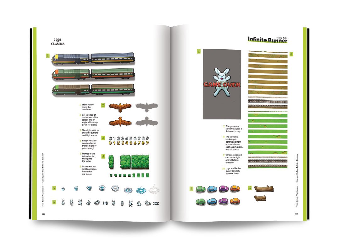
Get your copy of Code the Classics today
You can download the code for all the Code the Classics Volume 1 games here. Click on Clone or Download > Download ZIP. Unzip the download somewhere.
You’ll need Python 3 with Pygame Zero installed. The process for this differs a little between different computers, but there’s a good overview of all the different options on page 186 of Code the Classics.
Subscribe to HackSpace magazine for twelve months and you get a Circuit Playground Express for free! Then you can make your very own Infinite Bunner controller
Once everything’s set up, open a terminal and navigate to the directory you unzipped the code in. Then, inside that, you should find a folder called bunner-master and move into that. You can then run:
python3 bunner.py
Have a few goes playing the game, and you’ll find that you need the left, right, and up arrow keys to play (there is also the down arrow, but we’ve ignored this since we’ve never actually used it in gameplay – if you’re a Frogger/Bunner aficionado, you may wish to implement this as well).
Reading the accelerometer is as easy as importing the appropriate module and running one line:
from adafruit_circuitplayground import cpx, y, z = cp.acceleration
Sending key presses is similarly easy. You can set up a keyboard with the following:
from adafruit_hid.keyboard import Keyboard
from adafruit_hid.keyboard_layout_us import KeyboardLayoutUS
from adafruit_hid.keycode import Keycode

keyboard = Keyboard(usb_hid.devices)
Then send key presses with code such as this:
time.keyboard.press(Keycode.LEFT_ARROW) time.sleep(0.1)
keyboard.release_all()
The only thing left is to slot in our mechanics. The X-axis on the accelerometer can determine if the controller is tilted left or right. The output is between 10 (all the way left) and -10 (all the way right). We chose to threshold it at 7 and -7 to require the user to tilt it most of the way. There’s a little bit of fuzz in the readings, especially as the user flicks the controller up, so having a high threshold helps avoid erroneous readings.
The Y-axis is for jumping. In this case, we require a ‘flap’ where the user first lifts it up (over a threshold of 5), then back down again.
The full code for our controller is:
import time
from adafruit_circuitplayground import cp
import usb_hid
from adafruit_hid.keyboard import Keyboard
from adafruit_hid.keyboard_layout_us import KeyboardLayoutUS
from adafruit_hid.keycode import Keycode

keyboard = Keyboard(usb_hid.devices)

jumping = 0
up=False
while True:
    x, y, z = cp.acceleration
    if abs(y) > 5:
        up=True
    if y < 5 and up:
        keyboard.press(Keycode.UP_ARROW)
        time.sleep(0.3)
        keyboard.release_all()
        up=False
    if x < -7 :
        keyboard.press(Keycode.LEFT_ARROW)
        time.sleep(0.1)
        keyboard.release_all()
    if x < 7 : keyboard.press(Keycode.RIGHT_ARROW)
        time.sleep(0.1)
        keyboard.release_all()
        time.sleep(0.1)
    if jumping > 0:
        jumping=jumping-1
It doesn’t take much CircuitPython to convert a microcontroller into a games controller
The final challenge we had was that there’s a bit of wobble when moving the controller around – especially when trying to jump repeatedly and quickly. After fiddling with thresholds for a while, we found that there’s a much simpler solution: increase the weight of the controller. The easiest way to do this is to place it inside a book. If you’ve ever held a copy of Code the Classics, you’ll know that it’s a fairly weighty tome. Just place the board inside and close the book around it, and all the jitter disappears.
That’s all there is to the controller. You can use it to play the game, just as you would any joypad. Start the game as usual, then start flapping the book around to get hopping.
The latest issue of HackSpace magazine is out today and can be purchased from the Raspberry Pi Press online store. You can also download a copy if you want to see what all the fuss is about.
Code the Classics is available from Raspberry Pi Press as well, and comes with free UK shipping. And here’s a lovely video about Code the Classics artist Dan Malone and the gorgeous artwork he created for the book:
Code the Classics: Artist Dan Malone
No Description
The post Build a physical game controller for Infinite Bunner appeared first on Raspberry Pi.
Day three of our Pong celebration leads us here, to HackSpace magazine’s ultrasonic hack of Eben’s Code the Classics Pong tribute, Boing!
If you haven’t yet bought your copy of Code the Classics, you have until 11:59pm GMT tonight to get £1 off using the discount code PONG. Click here to visit the Raspberry Pi Press online store to secure your copy, and read on to see how you can use ultrasonic sensors to turn this classic game into something a lot more physical.
Over to the HackSpace magazine team…
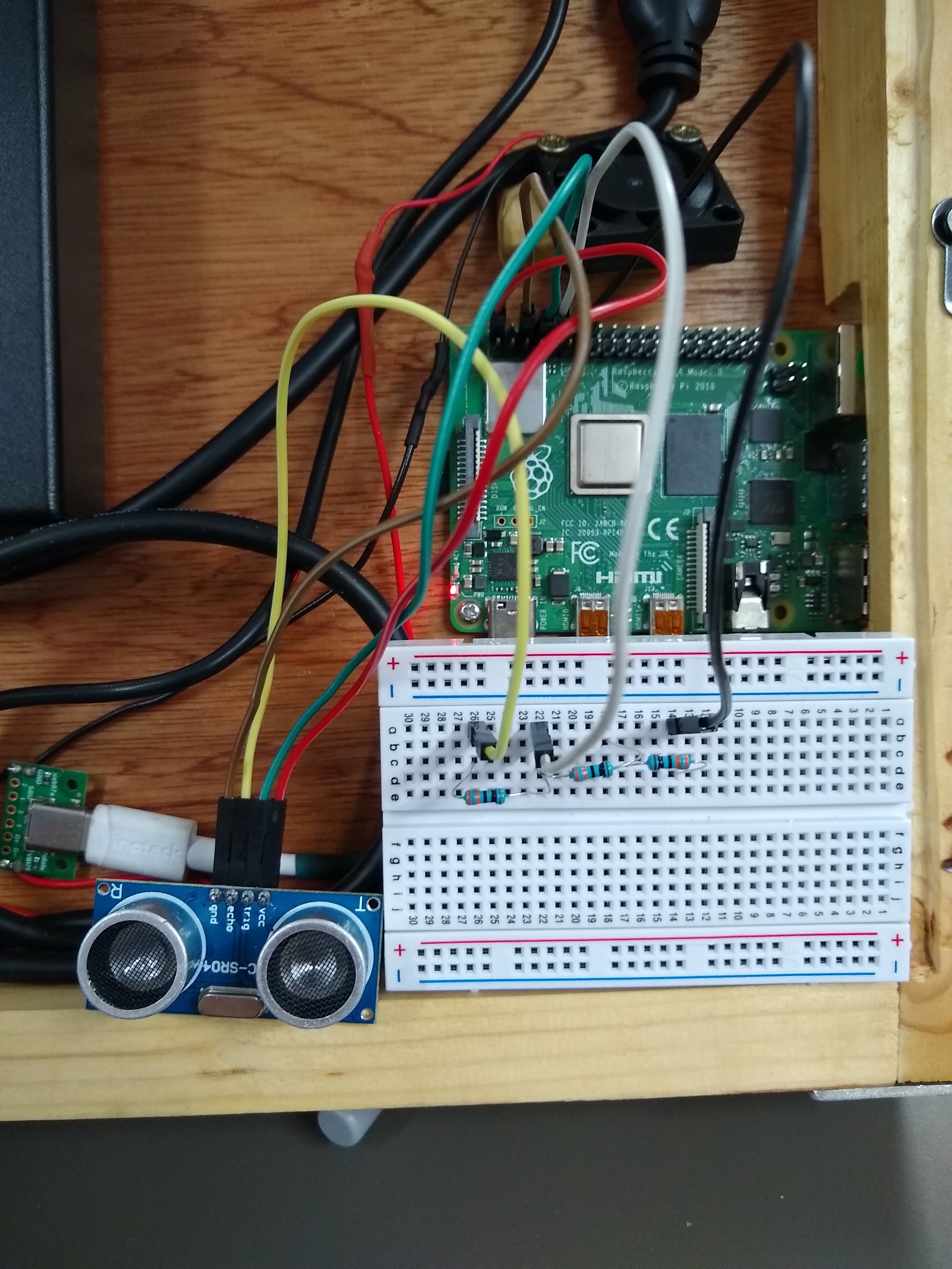
Code the Classics is an entertaining book for a whole bunch of reasons, but one aspect of it that is particularly exciting to us makers is that it means there are some games out there that are really fun to play, but also written to be easy to understand and have high-quality game art to go along with them. Why does this excite us as makers? Because it makes them ideal candidates for testing out novel DIY games controllers!
We’re going to start right at the beginning of the book (and also at the beginning of computer game history) with the game Pong. There’s a great chapter on this seminal game in the book, but we’ll dive straight into the source code of our Boing! tribute game. This code should run on any computer with Python 3 (and a few dependencies) installed, but we’ll use a Raspberry Pi, as this has GPIO pins that we can use to add on our extra controller.
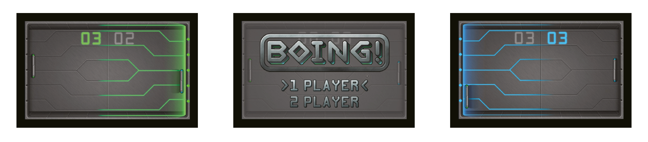
Download the code here by clicking the ‘Clone or download’ button, and then ‘Download ZIP’. Unzip the downloaded file, and you should have a directory called Code‑The‑Classics-master, and inside this, a directory called boing-master.
Open a terminal and navigate to this directory, then run:
python3 boing.py
If everything works well, you’ll get a screen asking you to select one or two players – press SPACE to confirm your selection, and have a play.
So that’s how Eben Upton designed the game to be played. Let’s put our own spin on it. Games controllers are basically just sensors that take input from the real world in some way and translate that into in-game actions. Most commonly, these sensors are buttons that you press, but there’s no need for that to be the case. You can use almost any sensor you can get input from – it sounds trite, but the main limitation really is your imagination!
We were playing with ultrasonic distance sensors in the last issue of HackSpace magazine, and this sprung to mind a Pong controller. After all, distance sensors measure in one dimension and Pong bats travel in one dimension.
Last issue we learned that the main challenge when using the cheap HC-SR04 sensors with 3.3V devices is that they use 5V, so we need to reduce their output to 3.3V. A simple voltage divider does the trick, and we used three 330Ω resistors to achieve this – see Figure 1 for more details.
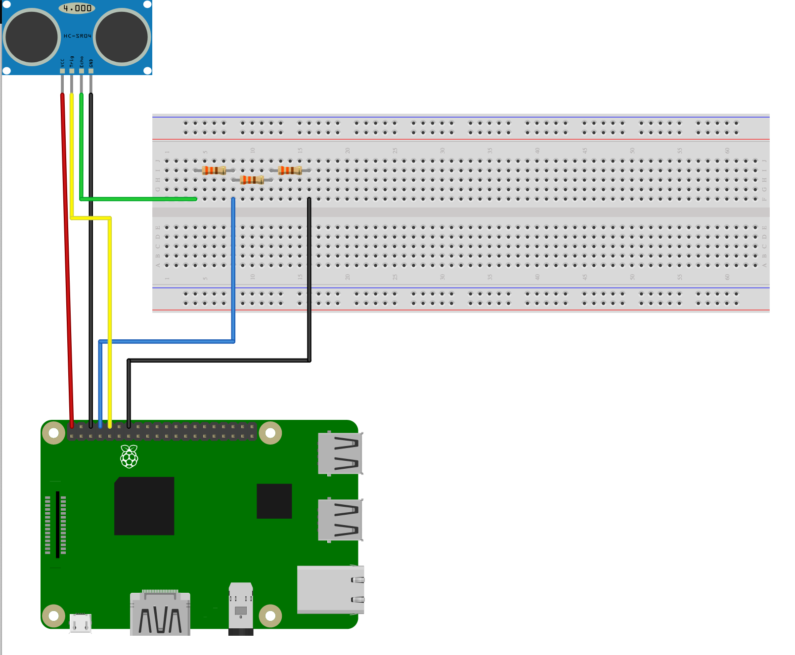
There’s support for these sensors in the GPIO Zero Python library. As a simple test, you can obtain the distance with the following Python code:
import gpiozero
import time
sensor = gpiozero.DistanceSensor(echo=15,trigger=14)

while True:
    print(sensor.distance)

time.sleep(0.1)
That will give you a constant read-out of the distance between the ultrasonic sensor and whatever object is in front of it. If you wave your hand around in front of the sensor, you’ll see the numbers changing from 0 to 1, which is the distance in metres.
So far, so straightforward. We only need to add a few bits to the code of our Boing! game to make it interact with the sensor. You can download an updated version of Boing! here, but the changes are as follows.
Add this line to the import statements at the top:
import gpiozero
Add this line to instantiate the distance sensor object at the end of the file (just before pgzrun.go()):
p1_distance = DistanceSensor(echo=15,trigger=14,queue_len=5)
We added the queue_len parameter to get the distances through a little quicker.
Finally, overwrite the p1_controls function with the following:
def p1_controls():
    move = 0
    distance = p1_distance.distance
    print(distance)
    if distance < 0.1:
        move = PLAYER_SPEED
    elif distance > 0.2:
        move = -PLAYER_SPEED
    return move
This uses the rather arbitrary settings of 10 cm and 20 cm to define whether the paddle moves up or down. You can adjust these as required.
That’s all there is to our ultrasonic Pong. It’s great fun to play, but there are, no doubt, loads of other versions of this classic game you can make by adding different sensors. Why not see what you can come up with?
Today is the last day to get £1 off Code the Classics with the promo code PONG, so visit the Raspberry Pi Press online store to order your discounted copy before 11:59pm GMT tonight.

You can also download Code the Classics as a free PDF here, but the book, oh, the book – it’s a marvellous publication that deserves a physical presence in your home.
The post Play Pong with ultrasonic sensors and a Raspberry Pi | HackSpace magazine appeared first on Raspberry Pi.
If your amazing project is a little too quiet, add high-fidelity sound with Raspberry Pi and the help of this handy guide from HackSpace magazine, written by PJ Evans.
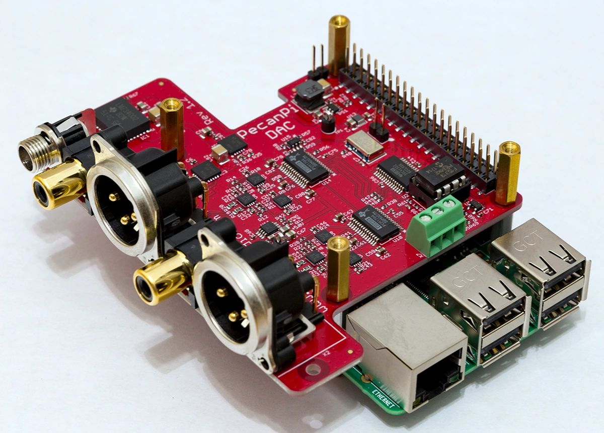
The PecanPi HAT features best-in-class components and dual DACs for superior audio reproduction
It’s no surprise that we love microcontrollers at HackSpace magazine. Their versatility and simplicity make them a must for electronics projects. Although a dab hand at reading sensors or illuminating LEDs, Arduinos and their friends do struggle when it comes to high-quality audio. If you need to add music or speech to your project, it may be worth getting a Raspberry Pi computer to do the heavy lifting. We’re going to look at the various audio output options available for our favourite small computer, from a simple buzz, through to audiophile bliss.

Need to keep it simple and under a pound?
An active buzzer is what you need
The simplest place to start is with the humble buzzer. A cheap active buzzer can be quickly added to Raspberry Pi’s GPIO. It’s surprisingly easy too. Try connecting a buzzer’s red wire (positive) to GPIO pin 22 (Broadcom numbering) and the black wire (ground) to any GND pin. Now, install the GPIO Zero Python library by typing this at the command line:
sudo apt install python3-gpiozero
Create a file called buzz.py in your favourite editor and enter the following:
import time
from gpiozero import Buzzer
buzzer = Buzzer(22)
buzzer.on()
time.sleep(1)
buzzer.off()
Run it at the command line:
python3 buzz.py
You should hear a one-second buzz. See if you can make Morse code sounds by changing the duration of the sleep statement.
Raspberry Pi computers, with the exception of the Zero range, all have audio output on board. The original Raspberry Pi featured a stereo 3.5mm socket, and all A and B models since feature a four-pole socket that also includes composite video. This provides your cheapest route to getting audio from your Raspberry Pi computer.
A low-cost passive speaker can be directly plugged in to provide sound, albeit probably quieter than you’d like. Of course, add an amplifier or active speaker and you have sound as loud as you like. This is the most direct way of adding sound to your project, but how to get the sound out?
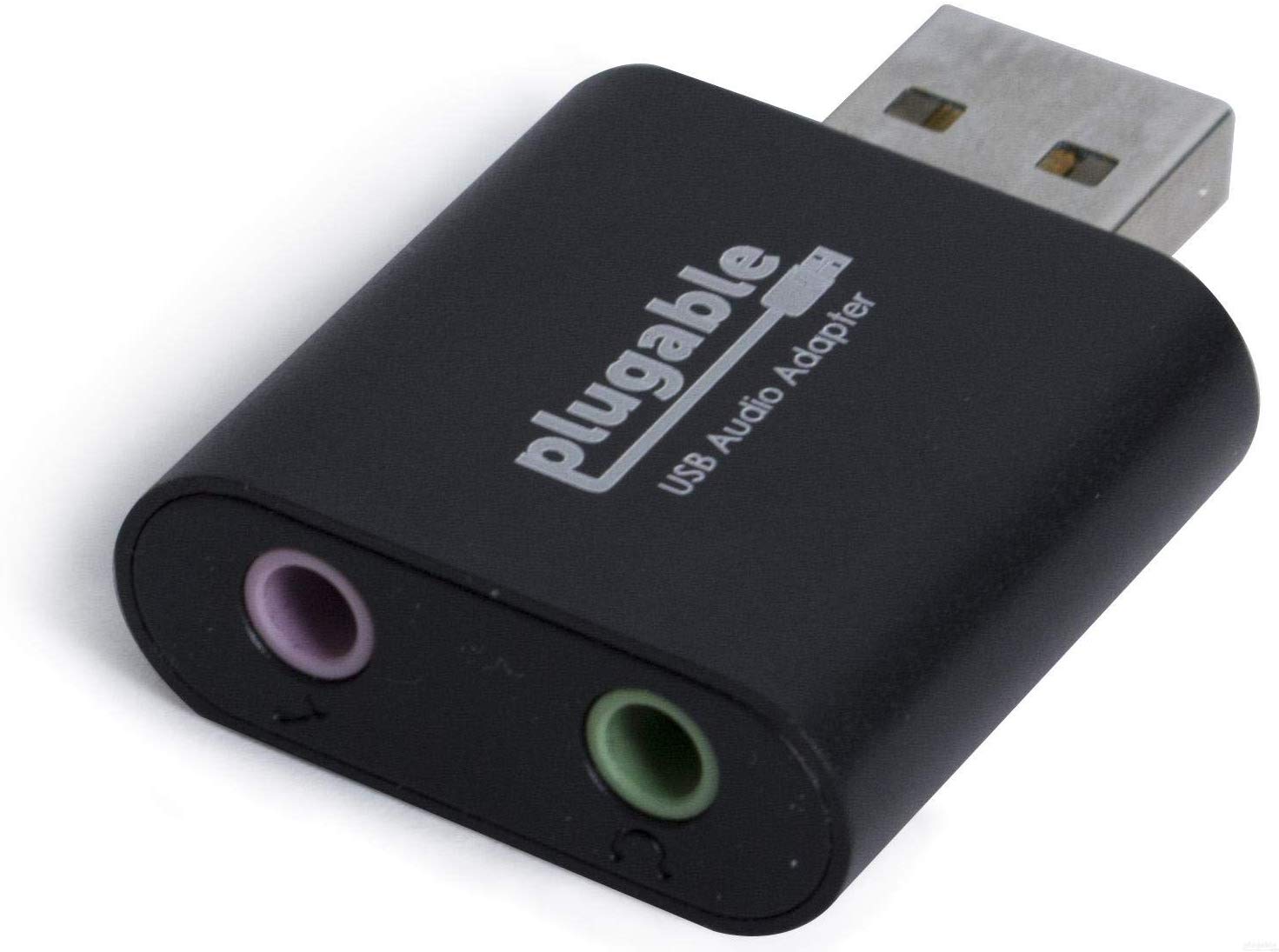
Need a simple solution? USB audio devices come in all shapes and sizes but are mostly plug-and-play
Normally, the Raspbian operating system will recognise that an audio device has been connected and route audio through it. Sometimes, especially if you’ve connected an HDMI monitor with sound capability (e.g. an HDMI TV), sound will not come out of the correct device.
To fix this, open up a terminal window and run sudo raspi-config. When the menu appears, go to Advanced Options and select Audio, then select the option to force the output through the audio jack. You may need to reboot Raspbian for all changes to take effect.
A USB sound device is another simple choice for audio playback on Raspberry Pi. Literally hundreds are available, and a basic input/output device with better audio quality than the on-board system can be purchased for a few pounds online. Installation tends to be no more complicated than plugging the device into the USB port. You may need to select the new output, as the underlying audio system, ALSA (see the ALSA and PulseAudio section for more), may mute it by default. To fix this, run alsamixer from the command line, press F6 to select the new sound device, and if you see ‘MM’ at the bottom of the volume indicator, press M to unmute and adjust the volume with the cursor keys.
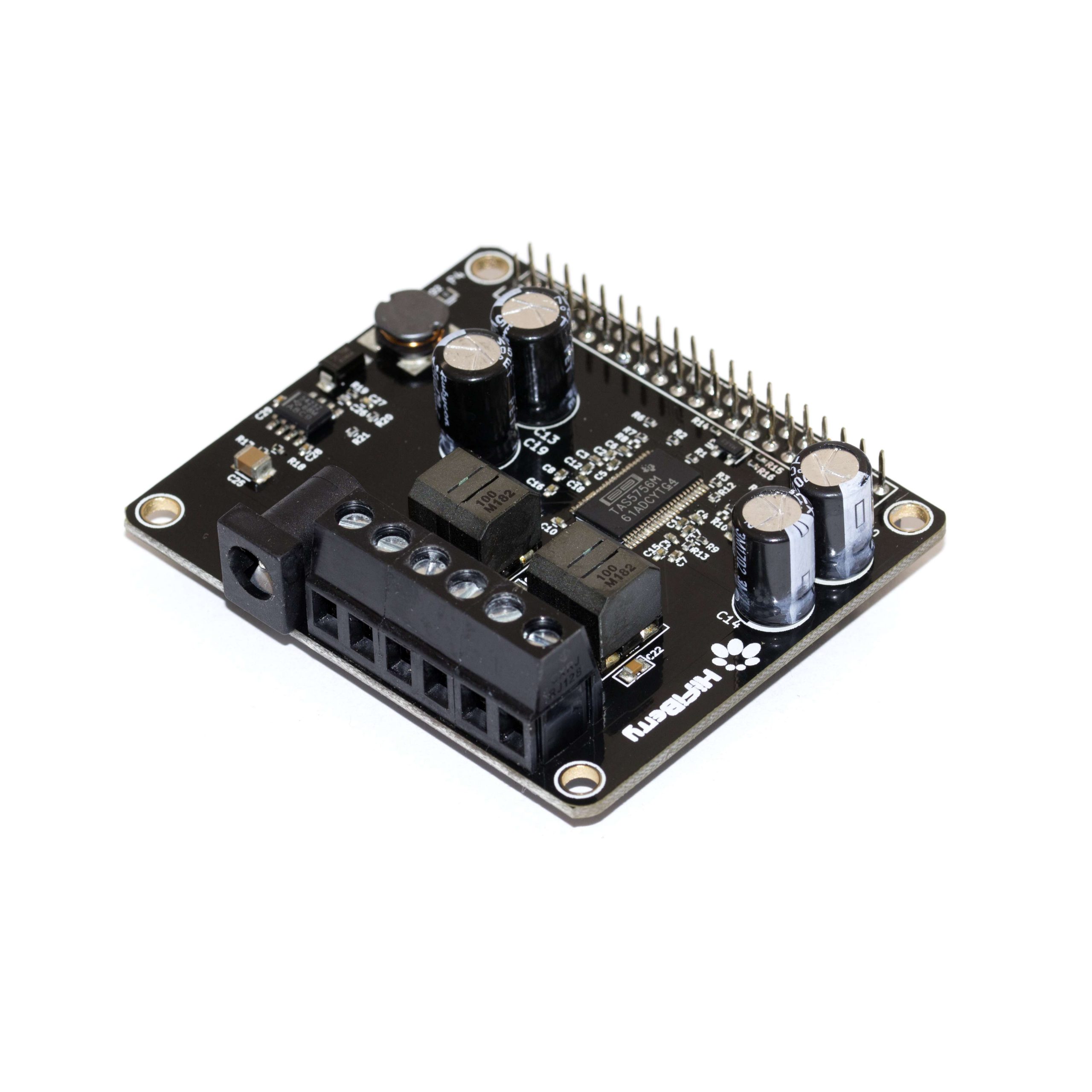
Many DACs also come with on-board amplifiers. Perfect for passive speakers
Unsurprisingly, when choosing your USB sound device, you can start at a few pounds and go right up to professional equipment costing hundreds. As they are low-power, USB devices do not tend to feature amplification, unless they have a separate power source.
The simplest way to play audio on Raspbian is to use OMXPlayer. This is a dedicated hardware-accelerated command-line tool that takes full advantage of Raspberry Pi’s capabilities. It sends audio to the analogue audio jack by default, so playing back an MP3 file is as simple as running:
omxplayer /path/to/audio/file.wav
There are many command-line options that allow you to control how the audio is played. Want the audio to loop forever? Just add --loop to the command. You’ll notice that when it’s running, OMXPlayer provides a user interface of sorts, allowing you to control playback from within the terminal. If you’d just like it to run in the background without user input, run the command like this:
omxplayer --no-keys example.wav &
Here, —-no-keys removes the interface, and the ampersand (&) tells the operating system to run the job ‘in the background’ so that it won’t block anything else you want to do.
OMXPlayer is a great choice for Raspbian, but other players such as mpg321 are available, so find the tool that’s best for you.
Another useful utility is speaker-test. This can produce white noise or vocal confirmation so you can check your speakers are working properly. It’s as simple as this:
speaker-test -t wav -c 2
The first parameter sets the sound to be a voice, and the -c tests stereo channels only: front left and front right.
If space is an issue, a Raspberry Pi 4, amplifier, and speaker may not be what you have in mind. After all, your cool wearable project is going to be problematic if you’re trailing an amplifier on a cart with a 50-metre extension lead powering everything. Luckily, the clever people at Pimoroni have you covered. The Speaker pHAT is a Raspberry Pi Zero-sized HAT that not only adds audio capability to the smallest of the Raspberry Pi family, but also sports a 3 W speaker. Now you can play any audio with a tiny device and a USB battery pack.
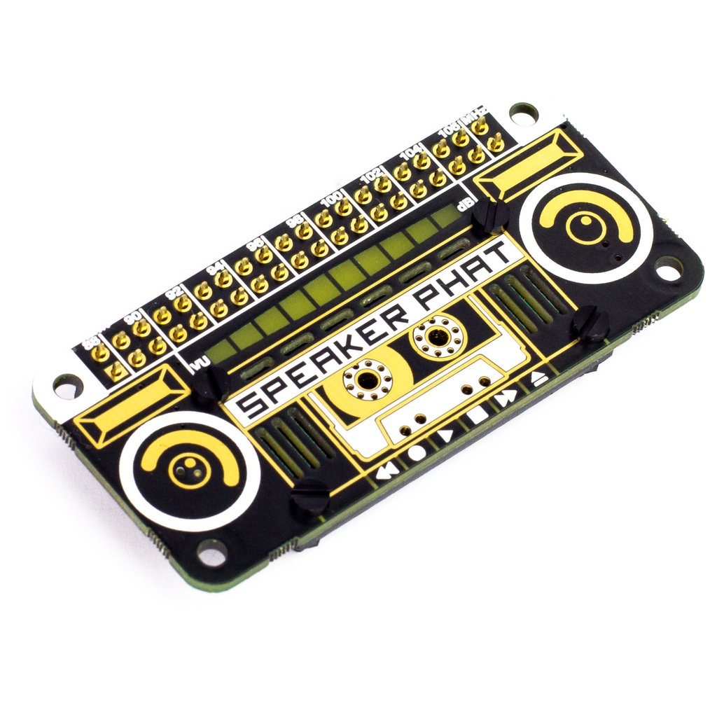
Small, cheap, and fun, the Speaker pHat features a 3 W speaker and LED VU meter
The installation process is fully automated, so no messing around with drivers and config files. Once the script has completed, you can run any audio tool as before, and the sound will be routed through the speaker. No, the maximum volume won’t be troubling any heavy metal concerts, but you can’t knock the convenience and form factor.
An easy way to get superior audio quality using a Raspberry Pi computer is Bluetooth. Recent models such as the 3B, 4, and even the Zero W support Bluetooth devices, and can be paired with most Bluetooth speakers, even from the command line. Once connected, you have a range of options on size and output power, plus the advantage of wireless connectivity.
Setting up a Bluetooth connection, especially if you are using the command line, can be a little challenging (see the Bluetooth cheatsheet section). There is a succinct guide here: hsmag.cc/N6p2IB. If you are using Raspbian Desktop, it’s a lot easier. Simply click on the Bluetooth logo on the top-right, and follow the instructions to pair your device.
If you find OMXPlayer isn’t outputting any audio, try installing mpg321:
sudo apt install mpg321
And try again:
mpg321 /path/to/audio/file.mp3
If your project needs good audio, and the standard 3.5 mm output just isn’t cutting it, then it’s time to look at the wide range of DACs (digital-to-analogue converters) available in HAT format. It’s a crowded market, and the prices vary significantly depending on what you want from your device. Let’s start at the lower end, with major player HiFiBerry’s DAC+ Zero. This tiny HAT adds 192kHz/24-bit playback via two RCA phono ports for £12.50. If you’re serious about your audio, then you can consider the firm’s full HAT format high-resolution DAC+ Pro for £36, or really go for it with the DSP (digital sound processing) version for £67. All of these will require amplification, but the sound quality will rival audio components of a much higher price.
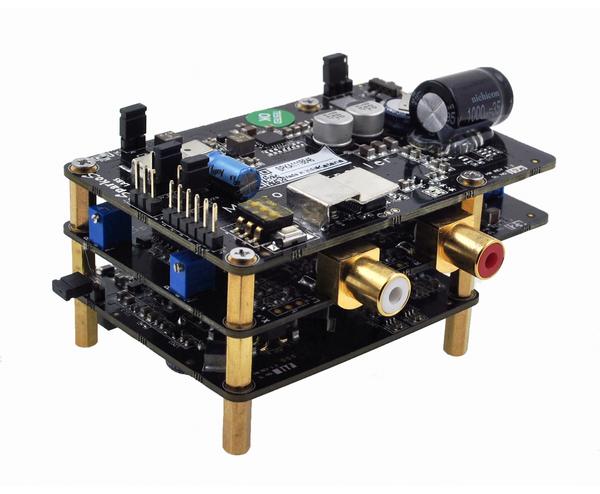
Money no object? The Allo Katana is a monster DAC, and weighs in at £240, but outperforms £1000 equivalents
If money is no object and your project requires the best possible reproduction, then you can consider going full audiophile. There are some amazing high-end HATs out there, but one of the best-performing ones we’ve seen is the PecanPi DAC. Its creator Leonid Ayzenshtat sourced each individual component carefully, always choosing the best-in-class. He even used a separate DAC for each audio channel. The resulting board may make your wallet wince at around £200 for the bare board, but the resulting audio is good enough to be used in professional recording studios. If you’ve restored a gorgeous old radio back to showroom condition, you could do a lot worse than add the board in with a great amp and speaker.
There’s often confusion between these two systems. Raspbian comes pre-installed with ALSA (Advanced Linux Sound Architecture), which is the low-level software that makes sound work. It comes with a range of utilities to control output device, volume, and more. PulseAudio is a software layer that sits on top of ALSA to provide more features, including streaming capabilities. Chances are, if you need to do something a bit more clever than just play audio, you’ll need to install a PulseAudio server.
If you want to pair a Bluetooth audio device (A2DP) on the command line, it can be a little hairy. Here’s a quick guide:
First-time installation:
sudo apt-get install pulseaudio pulseaudio-module-bluetooth
sudo usermod -G bluetooth -a pi
sudo reboot
Start the PulseAudio server:
pulseaudio --start
Run the Bluetooth utility:
bluetoothctl
Put your speaker into pairing mode. Now, within the utility, run the following commands (pressing Enter after each one):
power on
agent on
scan on
Now wait for the list to populate. When you see your device…pair <dev>
Where <dev> is the displayed long identifier for your device. You can just type in the first few characters and press Tab to auto-complete. Do the same for the following steps.
trust <dev>
connect <dev>
Wait for the confirmation, then enter:
quit <dev>
Now try to play some audio using aplay (for WAV files) or mpg321 (for mp3). These instructions are adapted from the guide by Actuino at hsmag.cc/N6p2IB.
There are command-line players available for just about every audio format in common use. Generally, MP3 provides the best balance of quality and space, but lower bit-rates result in lower sound quality. WAV is completely uncompressed, but can eat up your SSD card. If you don’t want to compromise on audio quality, try FLAC, which is identical in quality to WAV, but much smaller. To convert between audio types, consider installing FFmpeg, a powerful audio and video processing tool.
This article comes direct from HackSpace magazine issue 28, out now and available in print from your local newsagent, the Raspberry Pi Store in Cambridge, and online from Raspberry Pi Press.
If you love HackSpace magazine as much as we do, why not have a look at the subscription offers available, including the 12-month deal that comes with a free Adafruit Circuit Playground! Subscribers in the USA can now get a 12-month subscription for $60 when joining by the end of March!
![]()
And, as always, you can download the free PDF from the Raspberry Pi Press website.
The post How to play sound and make noise with your Raspberry Pi appeared first on Raspberry Pi.
Today we’re launching a time-limited special offer on subscriptions to HackSpace magazine and The MagPi magazine for readers in the USA, saving you a whopping 48% compared to standard overseas subscriptions. We want to help as many people as possible get their hands on our fantastic publications.
Starting today, you can subscribe to these magazines for the discounted price of $60 a year – just $5 per issue. Not only will you receive twelve issues direct to your door, but you’ll also receive a free gift and save up to 35% compared with newsstand prices!
You’ll need to be quick – this discounted offer is only running until 31 March 2020.
HackSpace magazine is packed with projects for fixers and tinkerers of all abilities. We’ll teach you new techniques and give you refreshers on familiar ones, from 3D printing, laser cutting, and woodworking to electronics and the Internet of Things. HackSpace magazine will inspire you to dream bigger and build better.

Your $60 subscription will get you twelve issues per year and a free Adafruit Circuit Playground Express, worth $25. Click here to subscribe today!
The MagPi is the official Raspberry Pi magazine. Written by and for the community, it’s packed with Raspberry Pi-themed projects, computing and electronics tutorials, how-to guides, and the latest news and reviews.

Your $60 subscription will get you twelve issues per year and a free Raspberry Pi Zero W with accessories. Click here to subscribe today!
To help spread the word about this special offer, we’re running a little no-purchase-required giveaway.
Just retweet this tweet with the hashtag #WinARaspberryPiThing, and we’ll pick five of you to win a Raspberry Pi bookazine of your choice, signed by whichever members of the Raspberry Pi team Alex can pull away from the scrum around the coffee machine.
If you don’t have Twitter, you can leave your favourite (family-friendly) knock-knock joke in the blog comments below and we’ll pick two more winners from there too!
The winners can choose any of the following:
We’ll pick winners on 1 April 2020, so you have a month and a bit to share the love!
The post USA magazine subscriptions offer: 48% off standard prices appeared first on Raspberry Pi.
How many types of infill pattern have you tried? The latest video from Raspberry Pi Press takes a closer look at 3D printing infill patterns, and why you may want to use a certain pattern over another.
3D PRINTING INFILL PATTERNS – What, why, and why not! || HackSpace magazine
There’s more than one option when it comes to selecting infill patters for your 3D prints. But what are the differences, and why should you use one over the other? #HackSpacemagazine is the monthly magazine for people who love to make things and those who want to learn.
Raspberry Pi Press publishes a variety of magazines and books, and the Raspberry Pi Press YouTube channel covers them all. Subscribe today to keep up to date with all new video releases, and let us know in the video comments what other content you’d like to see.
The post 3D printing infill patterns — what, why, and why not! appeared first on Raspberry Pi.
Our brand-new trailer for HackSpace magazine is very pretty. Here, have a look for yourself.
THIS IS MAKING || Hackspace magazine
HackSpace magazine is the new monthly magazine for people who love to make things and those who want to learn. Grab some duct tape, fire up a microcontroller, ready a 3D printer and hack the world around you!
As we mentioned last week, this month’s HackSpace magazine contains a very cool Raspberry Pi special feature that we know you’ll all love.
HackSpace magazine is available at major newsagents in the UK, at the Raspberry Pi store, Cambridge, at Barnes & Noble in the US, and in our online store.
You can also download the latest issue as a free PDF, so if you’re new to HackSpace, there really is no reason not to give it a go. We know you’re going to love it.
The post Our brand-new HackSpace magazine trailer appeared first on Raspberry Pi.
The latest issue of HackSpace magazine is out today, and it features a rather recognisable piece of tech on the front cover.
From personal computing and electronic fashion to robotics and automatic fabrication, Raspberry Pi is a rather adaptable piece of kit. And whether you choose to use the new Raspberry Pi 4, or the smaller, $5 Raspberry Pi Zero, there are plenty of projects out there for even the most novice of hobbyists to get their teeth into.
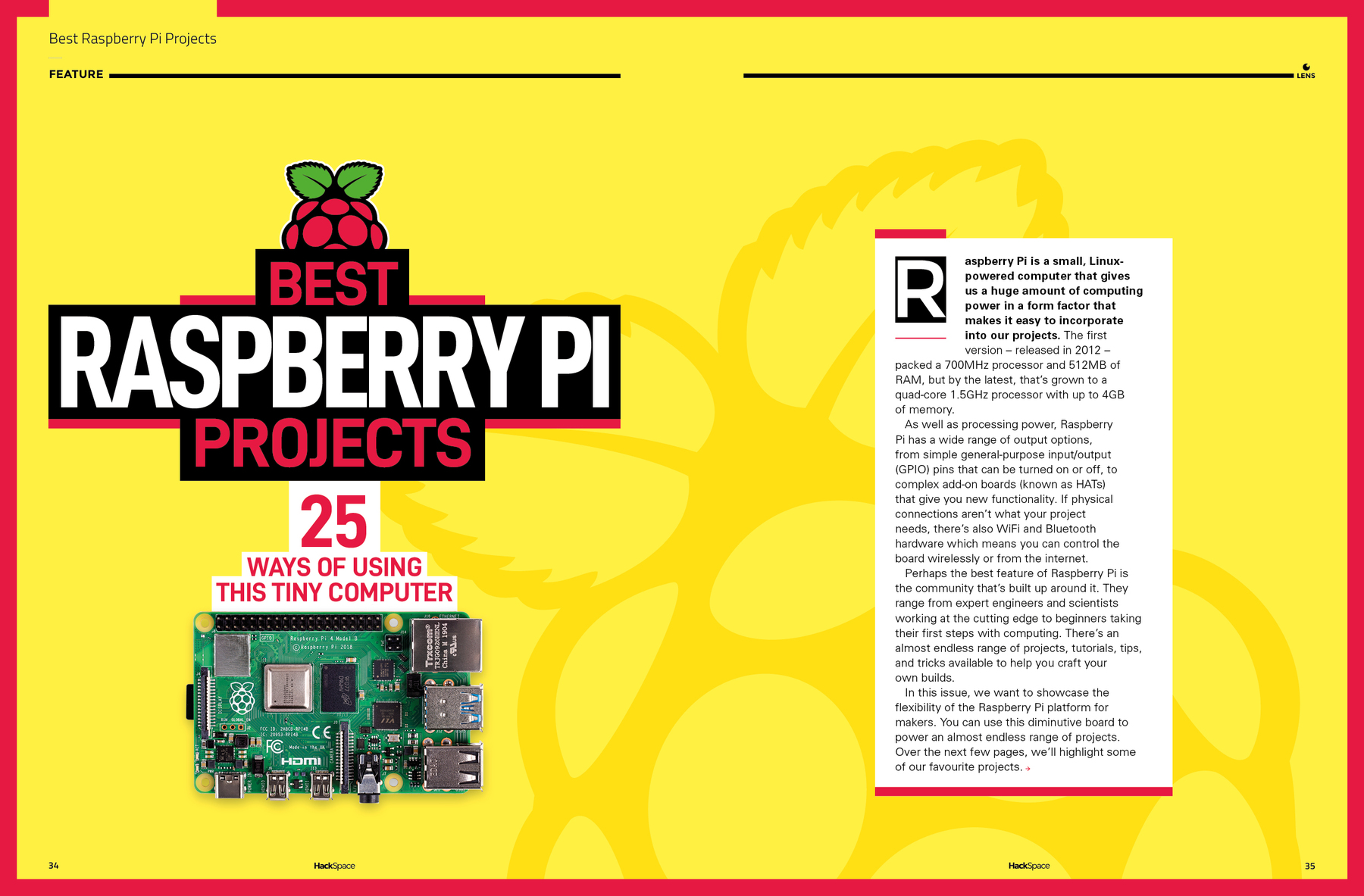
This month’s HackSpace magazine, a product of Raspberry Pi Press, is packed full of some rather lovely Raspberry Pi projects, as well as the magazine’s usual features from across the maker community. So, instead of us sharing one of the features with you, as we usually do on release day, we wanted to share them all with you.
Today’s new issue of HackSpace is available as a free PDF download, and, since you’re reading this post, I imagine you’re already a Raspberry Pi fan, so it makes sense you’ll also like this magazine.
So download the free PDF (the download button is below the cover image) and let us know what you think of HackSpace magazine in the comments below.
If you enjoy it and want to read more, you can get a HackSpace magazine subscription or purchase copies from Raspberry Pi Press online store, from the Raspberry Pi store, Cambridge, or from your local newsagent.

As with all our magazines, books, and hardware, every purchase of HackSpace magazine funds the charitable work of the Raspberry Pi Foundation. So if you enjoy this free PDF, please consider purchasing future issues. We’d really appreciate it.
The post HackSpace’s 25 ways to use a Raspberry Pi appeared first on Raspberry Pi.
If you own a 3D printer, you’ll likely have at least heard of OctoPrint, created by Gina Häußge and maintained by her and Guy Sheffer! OctoPrint has the potential to transform your 3D printing workflow for the better, and it’s very easy to set up. This guide will take you through the setup process step by step, and give you some handy tips along the way.

Before we start finding out how to install OctoPrint, let’s look at why you might want to. OctoPrint is a piece of open-source software that allows us to add WiFi functionality to any 3D printer with a USB port (which is pretty much all of them). More specifically, you’ll be able to drop files from your computer onto your printer, start/stop prints, monitor your printer via a live video feed, control the motors, control the temperature, and more, all from your web browser. Of course, with great power comes great responsibility — 3D printers have parts that are hot enough to cause fires, so make sure you have a safe setup, which may include not letting it run unsupervised.
• Raspberry Pi 3 (or newer)
• MicroSD card
• Raspberry Pi power adapter
• USB cable (the connector type will depend on your printer)
• Webcam/Raspberry Pi Camera Module (optional)
• 3D-printed camera mount (optional)
Before we get started, it is not recommended that anything less than a Raspberry Pi 3 is used for this project. There have been reports of limited success using OctoPrint on a Raspberry Pi Zero W, but only if you have no intention of using a camera to monitor your prints. If you want to try this with a Pi Zero or an older Raspberry Pi, you may experience unexpected print failures.
Firstly, you will need to download the latest version of OctoPi from the OctoPrint website. OctoPi (created by Guy Sheffer) is a Raspbian distribution that comes with OctoPrint, video streaming software, and CuraEngine for slicing models on your Raspberry Pi. When this has finished downloading, unzip the file and put the resulting IMG file somewhere handy.
Next, we need to flash this image onto our microSD card. We recommend using Etcher to do this, due to its minimal UI and ease of use; plus it’s also available to use on both Windows and Mac. Get it here: balena.io/etcher. When Etcher is installed and running, you’ll see the UI displayed. Simply click the Select Image button and find the IMG file you unzipped earlier. Next, put your microSD card into your computer and select it in the middle column of the Etcher interface.
Finally, click on Flash!, and while the image is being burned onto the card, get your WiFi router details, as you’ll need them for the next step.
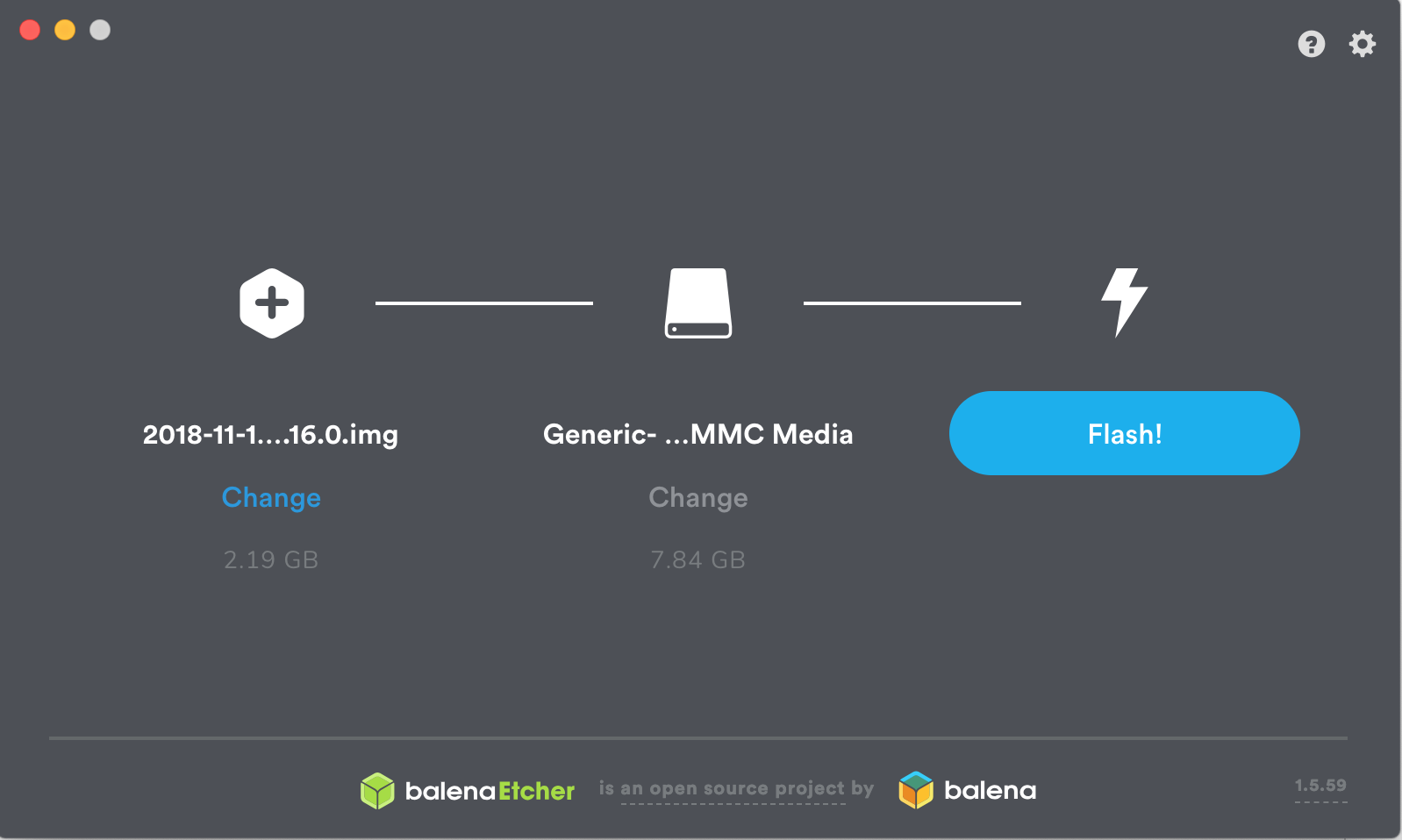
Now that you have your operating system, you’ll want to add your WiFi details so that the Raspberry Pi can automatically connect to your network after it’s booted. To do this, remove the microSD card from your computer (Etcher will have ‘ejected’ the card after it has finished burning the image onto it) and then plug it back in again. Navigate to the microSD card on your computer — it should now be called boot — and open the file called octopi-wpa-supplicant.txt. Editing this file using WordPad or TextEdit can cause formatting issues; we recommend using Notepad++ to update this file, but there are instructions within the file itself to mitigate formatting issues if you do choose to use another text editor. Find the section that begins ## WPA/WPA2 secured and remove the hash signs from the four lines below this one to uncomment them. Finally, replace the SSID value and the PSK value with the name and password for your WiFi network, respectively (keeping the quotation marks). See the example below for how this should look.
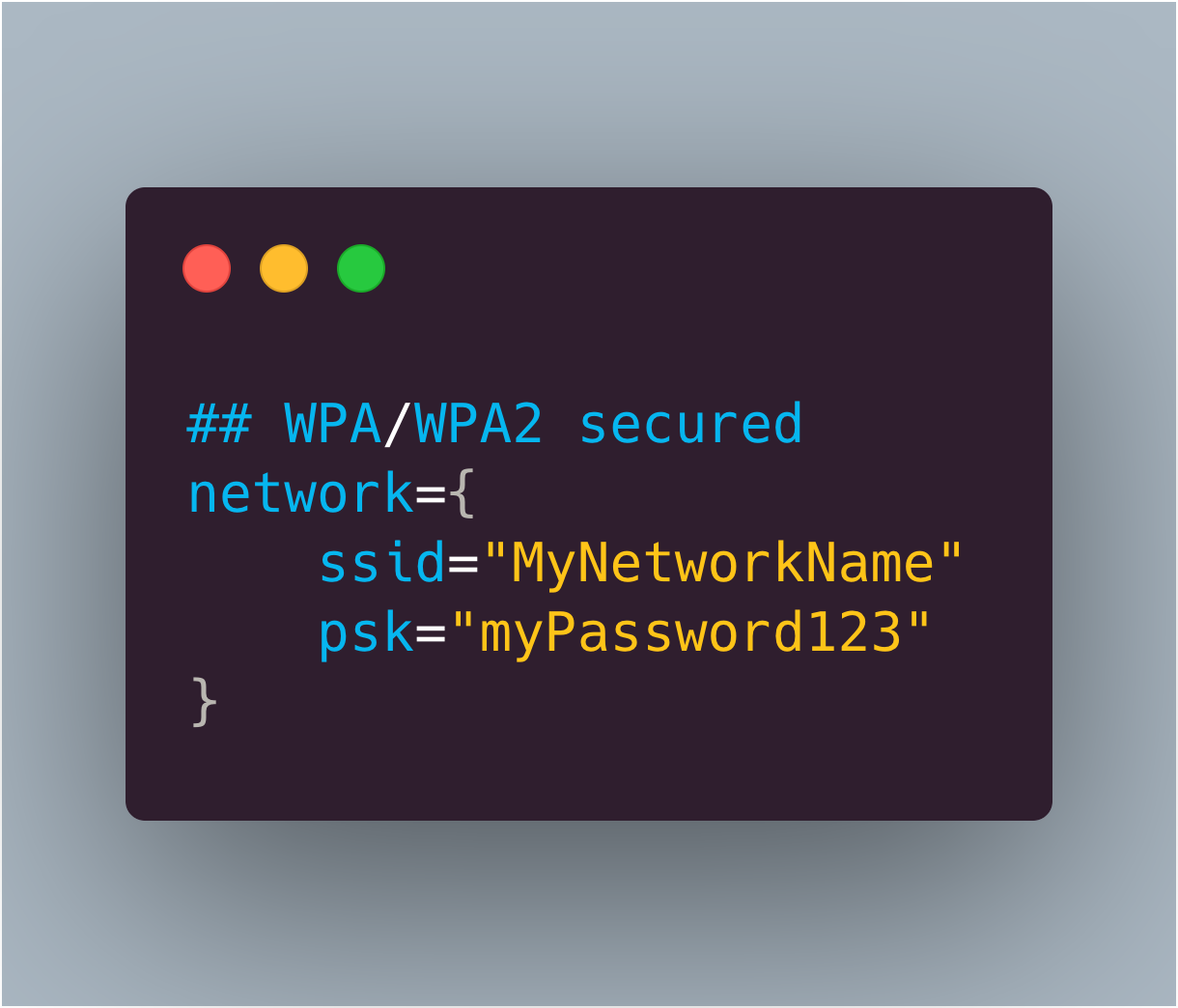
Further down in the file, there is a section for what country you are in. If you are using OctoPrint in the UK, leave this as is (by default, the UK is selected). However, if you wish to change this, simply comment the UK line again by adding a # before it, and uncomment whichever country you are setting up OctoPrint in. The example below shows how the file will look if you are setting this up for use in the US:
# Uncomment the country your Pi is in to activate Wifi in RaspberryPi 3 B+ and above
# For full list see: https://en.wikipedia.org/ wiki/ISO_3166-1_alpha-2
#country=GB # United Kingdom
#country=CA # Canada
#country=DE # Germany
#country=FR # France
country=US # United States
When the changes have been made, save the file and then eject/unmount and remove the microSD card from your computer and put it into your Raspberry Pi. Plug the power supply in, and go and make a cup of tea while it boots up for the first time (this may take around ten minutes). Make sure the Raspberry Pi is running as expected (i.e. check that the green status LED is flashing intermittently). If you’re using macOS, visit octopi.local in your browser of choice. If you’re using Windows, you can find OctoPrint by clicking on the Network tab in the sidebar. It should be called OctoPrint instance on octopi – double-clicking on this will open the OctoPrint dashboard in your browser.
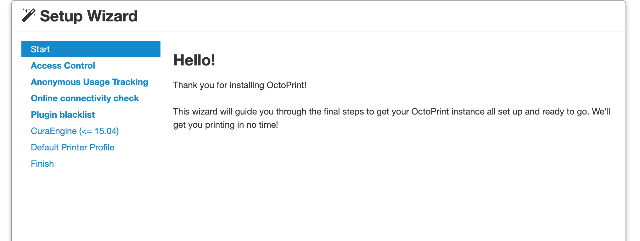
If you see the screen shown above, then congratulations! You have set up OctoPrint.
Not seeing that OctoPrint splash screen? Fear not, you are not the first. While a full list of issues is beyond the scope of this article, common issues include: double-checking your WiFi details are entered correctly in the octopi-wpa-supplicant.txt file, ensuring your Raspberry Pi is working correctly (plug the Raspberry Pi into a monitor and watch what happens during boot), or your Raspberry Pi may be out of range of your WiFi router. There’s a detailed list of troubleshooting suggestions on the OctoPrint website.
We now have the opportunity to set up OctoPrint for our printer using the handy wizard. Most of this is very straightforward — setting up a password, signing up to send anonymous usage stats, etc. — but there are a few sections which require a little more thought.
We recommend enabling the connectivity check and the plug-ins blacklist to help keep things nice and stable. If you plan on using OctoPrint as your slicer as well as a monitoring tool, then you can use this step to import a Cura profile. However, we recommend skipping this step as it’s much quicker (and you can use a slicer of your choice) to slice the model on your computer, and then send the finished G-code over.
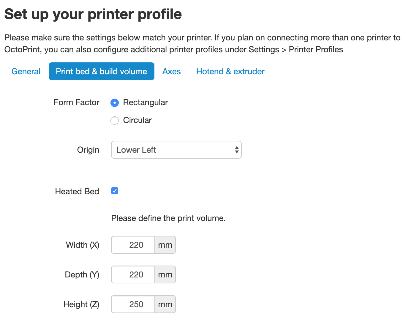
Finally, we need to put in our printer details. Above, we’ve included some of the specs of the Creality Ender-3 as an example. If you can’t find the exact details of your printer, a quick web search should show what you need for this section.
The General tab can have anything in it, it’s just an identifier for your own use. Print bed & build volume should be easy to find out — if not, you can measure your print bed and find out the position of the origin by looking at your Cura printer profile. Leave Axes as default; for the Hotend and extruder section, defaults are almost certainly fine here (unless you’ve changed your nozzle; 0.4 is the default diameter for most consumer printers).
Now that you’re set up with OctoPrint, you’re ready to start printing. Turn off your Raspberry Pi, then plug it into your 3D printer. After it has booted up, open OctoPrint again in your browser and take your newly WiFi-enabled printer for a spin by clicking the Connect button. After it has connected, you’ll be able to set the hot end and bed temperature, then watch as the real-time readings are updated.
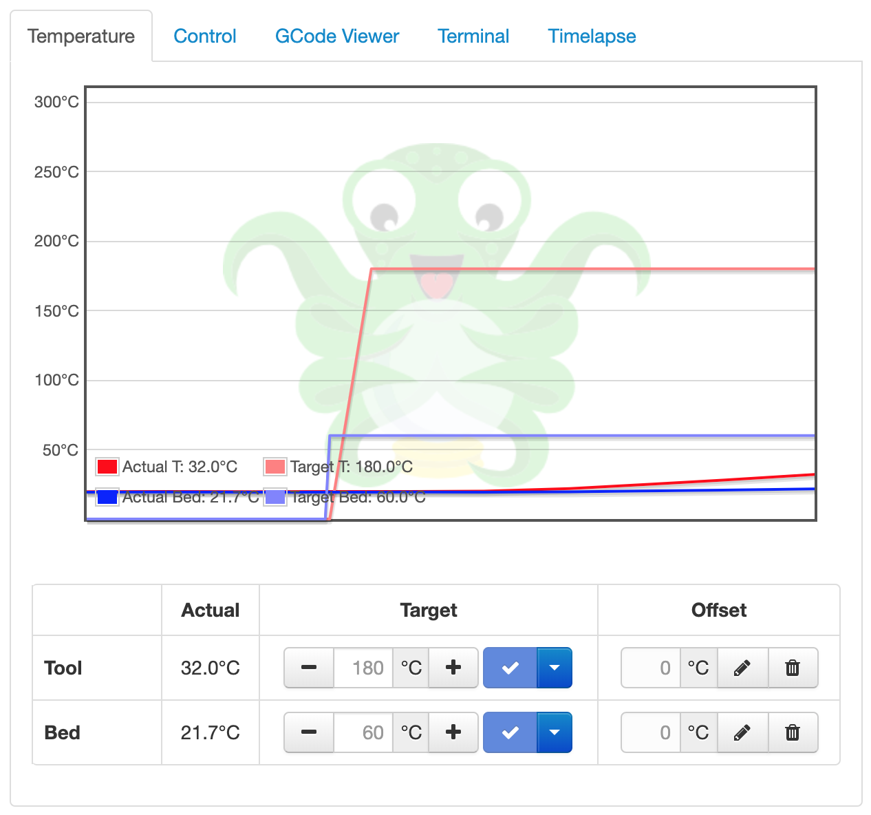
In the Control tab, we can see the camera stream (if you’re using one) and the motor controls, as well as commands to home the axes. There’s a G-code file viewer to look through a cross-section of the currently loaded model, and a terminal to send custom G-code commands to your printer. The last tab is for making time-lapses; however, there is a plug-in available to help with this process.
Undoubtedly the easiest way to set up video monitoring of your prints is to use the official Raspberry Pi Camera Module. There are dozens of awesome mounts on Thingiverse for a Raspberry Pi Camera Module, to allow you to get the best angle of your models as they print. There are also some awesome OctoPrint-themed Raspberry Pi cases to house your new printer brains. While it isn’t officially supported by OctoPrint, you can use a USB webcam instead if you have one handy, or just want some very high-quality video streams. The OctoPrint wiki has a crowdsourced list of webcams known to work, as well as a link for the extra steps needed to get the webcam working correctly.
As mentioned earlier, our recommended way of printing a model using OctoPrint is to first use your slicer as you would if you were creating a file to save to a microSD card. Once you have the file, save it somewhere handy on your computer, and open the OctoPrint interface. In the bottom left of the screen, you will see the Upload File button — click this and upload the G-code you wish to print.
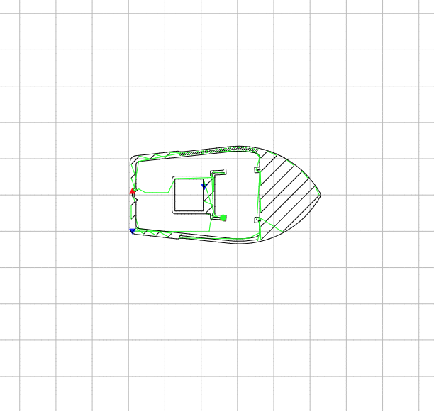
You’ll see the file/print details appear, including information on how long it’ll take for the object to print. Before you kick things off, check out the G-code Viewer tab on the right. You can not only scroll through the layers of the object, but, using the slider at the bottom, you can see the exact pattern the 3D printer will use to ‘draw’ each layer. Now click Print and watch your printer jump into action!
OctoPrint has scores of community-created plug-ins, but our favourite, Octolapse, makes beautiful hypnotic time-lapses. What makes them so special is that the plug-in alters the G-code of whatever object you are printing so that once each layer has finished, the extruder moves away from the print to let the camera take an unobstructed shot of the model. The result is an object that seems to grow out of the build plate as if by magic. You’ll not find a finer example of it than here.
Satisfying 3D Prints TimeLapse episode 7 (Prusa I3 Mk3 octopi)
3D Printing timelapses of models printed on the Prusa i3 MK3! Here’s another compilation of my recent timelapses. I got some shots that i think came out really great and i hope you enjoy them! as always if you want to see some of these timelapses before they come out or want to catch some behind the scenes action check out my instagram!
OctoPrint was created and is maintained by Gina Häußge (@foosel) and Guy Sheffer (@GuySoft)! A big thank you to both of them for putting in many, many volunteer hours to provide the world with an amazing piece of free, open-source software.
Head over to the OctoPrint website to find out how you can support OctoPrint’s continued existence.
This tutorial comes fresh from the pages of HackSpace magazine issue 26 and was written by Glenn Horan. Thanks, Glenn.
To get your copy of HackSpace magazine issue 26, visit your local newsagent, the Raspberry Pi Store, Cambridge, or the Raspberry Pi Press online store.
Fans of HackSpace magazine will also score themselves a rather delightful Adafruit Circuit Playground Express with a 12-month subscription. Sweet!
The post How to set up OctoPrint on your Raspberry Pi appeared first on Raspberry Pi.
You might have a baby/dog/hamster that you want to keep an eye on when you’re not there. We understand: they’re lovely, especially hamsters. Here’s how HackSpace magazine contributor Dr Andrew Lewis built a Raspberry Pi baby cam to watch over his small creatures…
When a project is going to be used in the home, it pays to take a little bit of extra time on appearance
You can get wireless baby monitors that have a whole range of great features for making sure your little ones are safe, sound, and sleeping happily, but they come with a hefty price tag.
In this article, you’ll find out how to make a Raspberry Pi-powered streaming camera, and combine it with a built-in I2C sensor pack that monitors temperature, pressure, and humidity. You’ll also see how you can use the GPIO pins on Raspberry Pi to turn an LED night light on and off using a web interface.
The hardware for this project is quite simple, and involves minimal soldering, but the first thing you need to do is to install Raspbian onto a microSD card for your Raspberry Pi. If you’re planning on doing a headless install, you’ll also need to enable SSH by creating an empty file called SSH on the root of the Raspbian install, and a file with your wireless LAN details called wpa_supplicant.conf.
You can download the code for this as well as the 3D-printable files from our GitHub. You’ll need to transfer the code to the Raspberry Pi. Next, connect the camera, the BME280 board, and the LEDs to the Raspberry Pi, as shown in the circuit diagram.
The BME280 module uses the I2C connection on pins 3 and 5 of the GPIO, taking power from pins 1 and 9. The LEDs connect directly to pins 19 and 20, and the camera cable fits into the camera connector.
Insert the microSD card into the Raspberry Pi and boot up. If everything is working OK, you should be able to see the IP address for your device listed on your hub or router, and you should be able to connect to it via SSH. If you don’t see the Raspberry Pi listed, check your wireless connection details and make sure your adapter is supplying enough power. It’s worth taking the time to assign your Raspberry Pi with a static IP address on your network, so it can’t change its IP address unexpectedly.
Use the raspi-config application to enable the camera interface and the I2C interface. If you’re planning on modifying the code yourself, we recommend enabling VNC access as well, because it will make editing and debugging the code once the device is put together much easier. All that remains on the software side is to update APT, download the babycam.py script, install any dependencies with PIP, and set the script to run automatically. The main dependencies for the babycam.py script are the RPi.bme280 module, Flask, PyAudio, picamera, and NumPy. Chances are that these are already installed on your system by default, with the exception of RPi.bme280, which can be installed by typing sudo pip3 install RPi.bme280 from the terminal. Once all of the dependencies are present, load up the script and give it a test run, and point your web browser at port 8000 on the Raspberry Pi. You should see a webpage with a camera image, controls for the LED lights, and a read-out of the temperature, pressure, and humidity of the room.
Finishing a 3D print by applying a thin layer of car body filler and sanding back will give a much smoother surface. This isn’t always necessary, but if your filament is damp or your nozzle is worn, it can make a model look much better when it’s painted
The easiest way to get the babycam.py script to run on boot is to add a line to the rc.local file. Assuming that the babycam.py file is located in your home directory, you should add the line python3 /home/pi/babycam.py to the rc.local file, just before the line that reads exit 0. It’s very important that you include the ampersand at the end of the line, otherwise the Python script will not be run in a separate process, the rc.local file will never complete, and your Raspberry Pi will never boot.
With the software and hardware working, you can start putting the case together. You might need to scale the 3D models to suit the tin can you have before you print them out, so measure your tin before you click Print. You’ll also want to remove any inner lip from the top of the can using a can opener, and make a small hole in the side of the can near the bottom for the USB power cable. Next, make a hole in the bottom of the can for the LED cables to pass through.
If you want to add more than a couple of LEDs (or want to use brighter LEDs), you should connect your LEDs to the power input, and use a transistor on the GPIO to trigger them
If you haven’t already done so, solder appropriate leads to your LEDs, and don’t forget to put a 330 Ω resistor in-line on the positive side. The neck of the camera is supported by two lengths of aluminium armature wire. Push the wire up through each of the printed neck pieces, and use a clean soldering iron to weld the pieces together in the middle. Push the neck into the printed top section, and weld into place with a soldering iron from underneath. Be careful not to block the narrow slot with plastic, as this is where the camera cable passes up through the neck and into the camera.
You need to mount the BME280 so that the sensor is exposed to the air in the room. Do this by drilling a small hole in the 3D-printed top piece and hot gluing the sensor into position. If you’re going to use the optional microphone, you can add an extra hole and glue the mic into place in the same way. A short USB port extender will give you enough cable to plug the USB microphone into the socket on your Raspberry Pi
Paint the tin can and the 3D-printed parts. We found that spray blackboard paint gives a good effect on 3D-printed parts, and PlastiKote stone effect paint made the tin can look a little more tactile than a flat colour. Once the paint is dry, pass the camera cable up through the slot in the neck, and then apply the heat-shrink tubing to cover the neck with a small gap at the top and bottom. Connect the camera to the top of the cable, and push the front piece on to hold it into place. Glue shouldn’t be necessary, but a little hot glue might help if the front parts don’t hold together well.
Push the power cable through the hole in the case, and secure it with a knot and some hot glue. Leave enough cable free to easily remove the top section from the can in future without stressing the wires.
If you’re having trouble getting the armature wire through the 3D-printed parts, try using a drill to help twist the wire through
Glue the bottom section onto the can with hot glue, and hot-glue the LEDs into place on the bottom, feeding the cable up through the hole and into the GPIO header. This is a good time to hot-glue a weight into the bottom of the can to improve its stability. I used an old weight from some kitchen scales, but any small weight should be fine. Finally, fix the Raspberry Pi into place on the top piece by either drilling or gluing, then reconnect the rest of the cables, and push the 3D-printed top section into the tin can. If the top section is too loose, you can add a little bit of hot glue to hold things together once you know everything is working.
With the right type of paint, even old tin cans make a good-looking enclosure
for a project
That should be all of the steps complete. Plug in the USB and check the camera from a web browser. The babycam.py script includes video, sensors, and light control. If you are using the optional USB microphone, you can expand the functionality of the app to include audio streaming, use cry detection to activate the LEDs (don’t make the LEDs too stimulating or you’ll never get a night’s sleep again), or maybe even add a Bluetooth speaker and integrate a home assistant.
HackSpace magazine is out now, available in print from your local newsagent, the Raspberry Pi Store in Cambridge, and online from Raspberry Pi Press.
If you love HackSpace magazine as much as we do, why not have a look at the subscription offers available, including the 12-month deal that comes with a free Adafruit Circuit Playground!
And, as always, you can download the free PDF here.
The post Raspberry Pi 3 baby monitor | Hackspace magazine #26 appeared first on Raspberry Pi.
Vim is my favorite text editor and version 8.2 released. The new version includes support for popup windows and text properties. Popup windows can be used for many purposes. For example, a list of choices can be displayed, where the user selects an entry with keys or with the mouse. There is also a new vim game released named as killersheep to show you new capabilities of Vim. Let us see how to install and play killersheep.![]()
The post killersheep – Silly game for Vim version 8.2 appeared first on nixCraft.